5.2.3 Electrical wiring
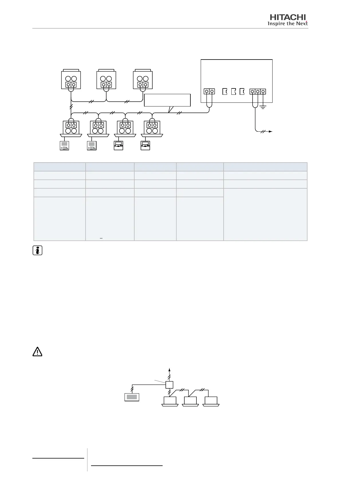
The central station requires wiring work for the power supply, air conditioner and control wiring (H-LINK) cables.
PSC-A32MN
1
CN1
1
2
2
FG
1
1 1 1
1
1 1
2
2 2 2
2
2
2
CN2 CN3
Outdoor unit
Remote control switch
Indoor unit
Power supply
100 to 240V
Frame ground
terminal
Terminal
board TB2
Terminal
board TB3
Terminal
board TB1
H-LINK
(Transmission wire)
Connect the transmission
wires to the TB terminals
and of the outdoor
units and the indoor units.
Type of wiring Specication Length of wiring Cable specication Recommended cable model
Power supply cable AC100 ~ 240V - 1.25 to 2 mm
2
600V CV, CCV, CEV (Hitachi Cable)
Earth wiring - - - -
H-LINK(Control wire) DC5V ≤1000 m 0.75 to 1.25 mm
2
JKPEV-S, JKEV-S,
CVV-S, CVV, 600V VCT
(Hitachi Cable)
Wiring for external in-
put and output
Input:
Non-voltage
normal open
Output: DC12V,
75mA>
≤300 m 0.5 to 1.25 mm
2
NOTE
• In case that a specied wire length is mentioned for the external input of transmission side, use either [1] the specied wire length of
transmission side or [2] 300 m, whichever is shorter.
• The central station may be damaged because of incorrect wiring.
• The controller may be damaged in case of performing wiring work with the main power turned ON.
Turn OFF the main power of the air conditioner and the controller before performing any wiring work.
• Transmission wires shall be separated from the power supply wiring and other electrical device wiring. Keep a separation of at least
30 cm between transmission wiring and the power supply wiring. If it is not possible to secure this space, then route the power sup-
ply wiring and transmission wiring through separate metal conduit tubes. One end of the metal conduit tubes shall be earthed for
noise reduction.
• Do not connect the power supply wiring to the terminals for transmission of central station. However, if the power supply wires are
connected incorrectly, the fuse of the printed circuit board will blow out for protection.
In such a case, turn ON pin 2 of DSW2 on the printed circuit board to allow emergency operation without the fuse.
• Always remove the earth wiring of “FG” terminal when performing insulation capacity test or withstand voltage test. Failure to do so
may result in damage to the central station.
CAUTION
When using an AC200V to 240V power supply.
Pull box
To outdoor unit or power
circuit breaker
Indoor units
• In case of using a 200V~240V power supply, diverge the main power supply cables by using a pull box as shown in the gure.
• The electricity supply to the unit should be via an exclusive power control switch and protective circuit breaker, certied and installed
in accordance with local or national safety regulations.
5 Centralised remote controls
PSC-A32MN
TCGB0106 rev.0 - 12/2014
296
 Loading...


