7 Gateways for building management systems
HARC-BX E
TCGB0106 rev.0 - 12/2014
677677
7
7-segment
display
Description
7-segment
display
Description
7-segment
display
Description
7-segment
display
Description
0
OU no. 01 or IU
no. 01
4
OU no. 05 or IU
no. 05
8
OU no. 09 or IU
no. 09
OU no. 13 or IU
no. 13
1
OU no. 02 or IU
no. 02
5
OU no. 06 or IU
no. 06
9
OU no. 10 or IU
no. 10
d
OU no. 14 or IU
no. 14
2
OU no. 03 or IU
no. 03
6
OU no. 07 or IU
no. 07
OU no. 11 or IU
no. 11
OU no. 15 or IU
no. 15
3
OU no. 04 or IU
no. 04
7
OU no. 08 or IU
no. 08
OU no. 12 or IU
no. 12
OU no. 16 or IU
no. 16
6 Put pin no. 2 of the 8 pin DIP switch (S202) in the OFF position when all the checks are completed.
The test mode is complete.
8 pin DIP switch setting
(S202)
7.4.5 Operation
7.4.5.1 Variables list
Communication with LonWorks interface
HARC-BX(A)
The HARC-BX(A) is a LonWorks interface designed for cases where only the control of the units is required and there is
no need for unit operation monitoring.
This interface allows the control of:
• Up to 64 indoor units and 8 outdoor units
• Up to 8 interfaces per H-Link
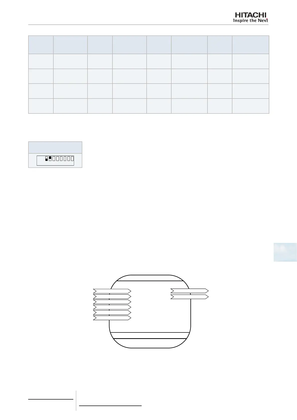
a. HARC-BX(A) communication mode:
The following variables can be controlled and monitored in each of the interface’s 8 PCBs:
nviOnOff_n
nviMode_n
nviSetPoint_n
nviFanSpeed_n
nviProtect_n
nviAllOnOff
nvoOnOff_n
nvoInletTemp_n
nciMaxSendTime
nciMinSendTime
x8 (each PCB)
7 Points Unit
Network variables Version 1.0A
Remote
Control
1 Common point
Monitor
Conguration properties

 Loading...


