7 Gateways for building management systems
HARC-BX E
TCGB0106 rev.0 - 12/2014
674674
7.4.3.4 DIP switch adjustment
The DIP switches are inside the central HARC-BX E control between the terminal board and the PCBs. The rst column of
DIP switches (S201) are used to programme the numbers of the outdoor units and indoor units, and the second column of
DIP switches (S202) are used to programme the master and slave controls.
There are two group of 8 DIP switches, which relate to the PCBs, the rst line of DIPs with the rst PCB and so on.
NOTE
The DIP switches are all deactivated before they are sent from the factory.
1 Congure the DIP switches before turning the power supply on.
2 Remove the front board to the congure the DIP switches.
3 Each board’s DIP switch conguration is different.
4 Set the 8 pin DIP switch (S201). The rst four pins of the 8 pin DIP switch (S201) are used to set the outdoor unit and
the second four pins are used to set the indoor units controlled by the PCB.
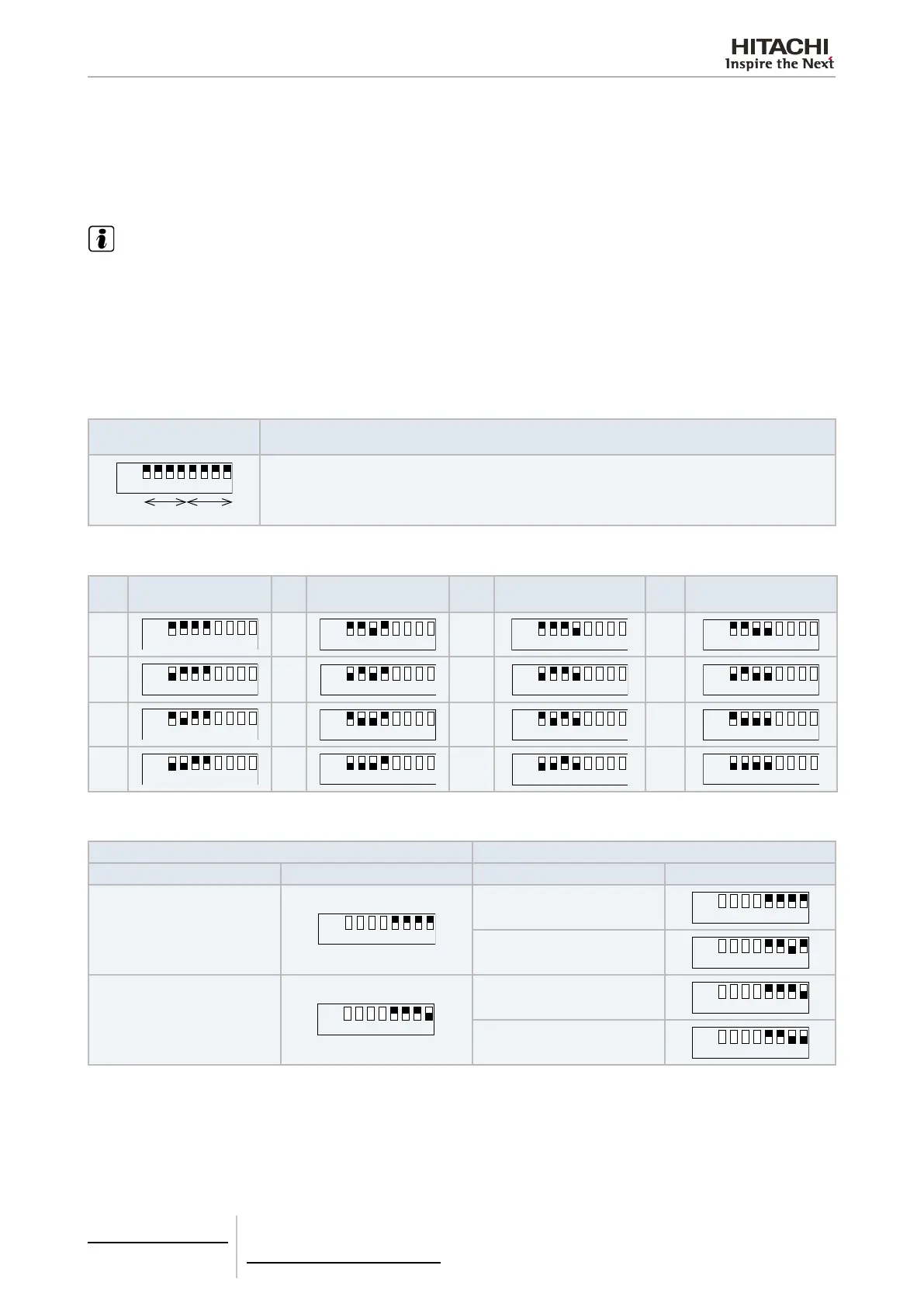
The setting procedure for the outdoor unit number and indoor unit number can be seen in the following table.
8 pin DIP switch setting
(S201)
Description
ON 1 2 3 4 5 6 7 8
No. IU
No. OU
The 8 pin DIP switch (S201) setting is determined by the numbers of the outdoor units (OU) and the
numbers of the corresponding indoor units (IU) controlled by the PCB.
The following table explains how to programme the outdoor unit numbers. Up to 16 numbers can be programmed:
OU
No.
Pin setting
OU
No.
Pin setting
OU
No.
Pin setting
OU
No.
Pin setting
0
4
8
12
1
5
9
13
2
6
10
14
3
7
11
15
The following table explains how to programme the numbers of the indoor units controlled for each board:
HARC-BX (A) HARC-BX (B)
Indoor units Pin setting Indoor units Pin setting
from 0 to 7
(8 IU)
ON 1 2 3 4 5 6 7 8
from 0 to 3
(4 IU)
from 4 to 7
(4 IU)
from 8 to 15
(8 IU)
ON 1 2 3 4 5 6 7 8
from 8 to 11
(4 IU)
from 12 to 15
(4 IU)
The position of the switch indicates the address of the rst indoor unit for this group of 8 units in the case of the HARC-
BX(A) or the rst indoor unit for the group of 4 units in the case of the HARC-BX(B).
Only the address indicated in the table above can be used for each group.
 Loading...


