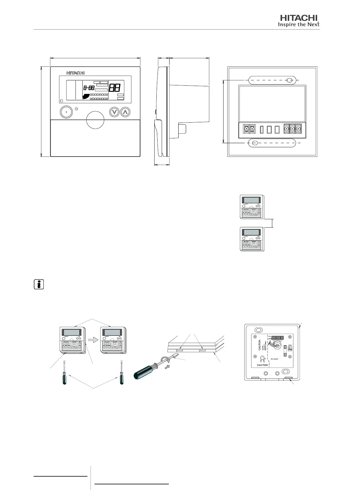
5.3.2.4 Dimensional data
83.5
20
RMT.SW NAVL
FILTER
ABNML
CHECK
EMERGENCY
DEMAND
TIMER
GROUP
9 10 11 12 13 14 15 16
1 2 3 4 5 6 7 8
HIGH
MED
LOW
LOUVER
NO FUNCTION
°C
TEMP.SET
COOL
AUTO
HEAT
DRY
FAN
AUTO
GROUP
RUN/STOP
(mm)
5.3.2.5 Installation space
If several control units are to be installed in a vertical position, leave a distance of
at least 50 mm between them to allow the front cover to be opened and to insert
the tool for removing the control from its housing.
At least 50 mm
5.3.2.6 Installation procedure
NOTE
Follow the national regulations for the right assembly of the PSC-A64S in the wall.
1 Using a at-head screwdriver, separate the control unit bracket from the front section as indicated below.
Screwdriver
Bracket
Groove
Central control
Screwdriver
Bracket
Groove
Bracket
Groove
5 Centralised remote controls
PSC-A64S
TCGB0106 rev.0 - 12/2014
372

 Loading...


