7 Gateways for building management systems
HARC-BX E
TCGB0106 rev.0 - 12/2014
687687
7
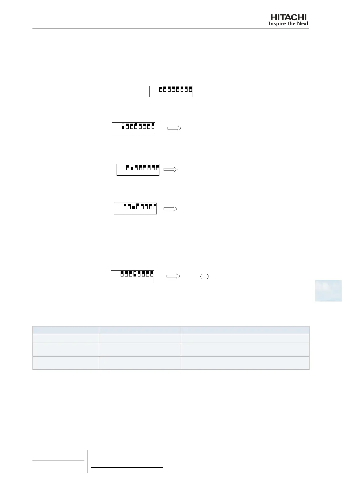
7.4.5.2 HARC-BX E self-check
The self-check, used to identify any abnormal conditions which may occur in the HARC-BX E, can be carried out with the
following procedures:
1 Connect the power supply leaving the 8 pin DIP switch (S202) in the OFF position. “88“ appears on the 7-segment
display and turns off).
8 pin DSW (S202)
2 Only put the 8 pin DIP switch (201) pin no. 1 in the ON position.
7-segment display
10 1
8 pin DSW (S201) Normal Abnormal
3 Put 8 pin DIP switch (201) pin no. 1 in the OFF position and then place only pin no. 2 in the ON position. (This action
should be carried out whilst also conguring the termination resistance of the terminal on the H-Link).
7-segment display
20 2
8 pin DSW (S201) Normal Abnormal
4 Put 8 pin DIP switch (201) pin no. 2 in the OFF position and then place only pin no. 3 in the ON position.
7-segment display
30*
8 pin DSW (S201)
* The total number of pins in the ON position out of pin numbers
1 to 5 of the 8 pin DIP switch (S202) will be shown on the right-
hand side of the display, and a number “3” will appear on the
left-hand side of the display
.
5 Put 8 pin DIP switch (201) pin no. 3 in the OFF position and then place only pin no. 4 in the ON position.
7-segment display
4- 88
8 pin DSW (S201) Normal Abnormal
7.4.5.3 Indication of abnormal conditions
1 Abnormal conditions will be displayed on the 7-segment display of the HARC-BX E.
7-segment display Phenomenon Type of abnormal condition
11
Abnormal initial connection. No remote control has been found (connection fault).
44
Abnormal transmission on the remote
control.
There has been no response 70 seconds after the attempted
transmission to the remote control.
61
Abnormal transmission on the remote
control.
There has been no response 180 seconds after the attempt-
ed transmission to the remote control.
 Loading...


