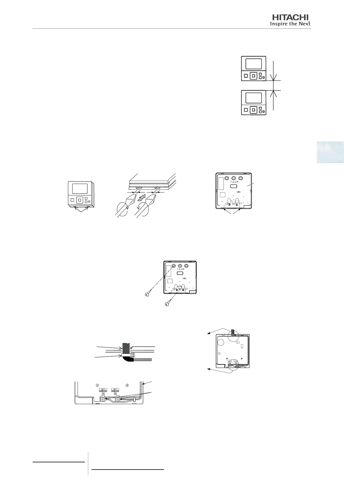
4.1.2.5 Installation space
In case of installing the controllers in vertical line, keep a distance more than 50mm
between the controllers vertically.
If the distance is insufcient, the controller can not be taken out.
>
4.1.2.6 Installation procedure
1 Insert the edge of the slotted screwdriver into the groove at the bottom of the holding bracket, push and turn the slotted
screw driver and then remove the remote control switch from the holding bracket.
Groove part
Approx. 6mm
Slotted
Screw driver
Figure seen from bottom side
Rear cover
Groove for attaching
controller
2 Attach the remote control switch to the holding bracket and connect the cable as follows:
In Case of Exposing Remote Control Cable
a. Fix the holding bracket onto the wall with screws (accessory).
b. Attach the stopper (plastic band) to the cable at the inside of the draw-out hole.
Cable
Band stopper
(Field-supplied)
Draw-out hole
Lead the cable with its
sheath peeled through
the groove.
Peel the insulation at
the end of the cable and
clamp the M3 solderless
terminals (field-supplied).
Lead the cable with its sheath peeled through the groove.
Peel the insulation at the end of the cable and clamp
the M3 solderless terminals (eld-supplied).
4 Individual remote controls
PC-ARF
TCGB0106 rev.0 - 12/2014
63
4
 Loading...


