8.3.3 Electrical wiring
In order to run, PC-A1IO must be connected to the corresponding input and output signals, power supply cables and H-
LINK.
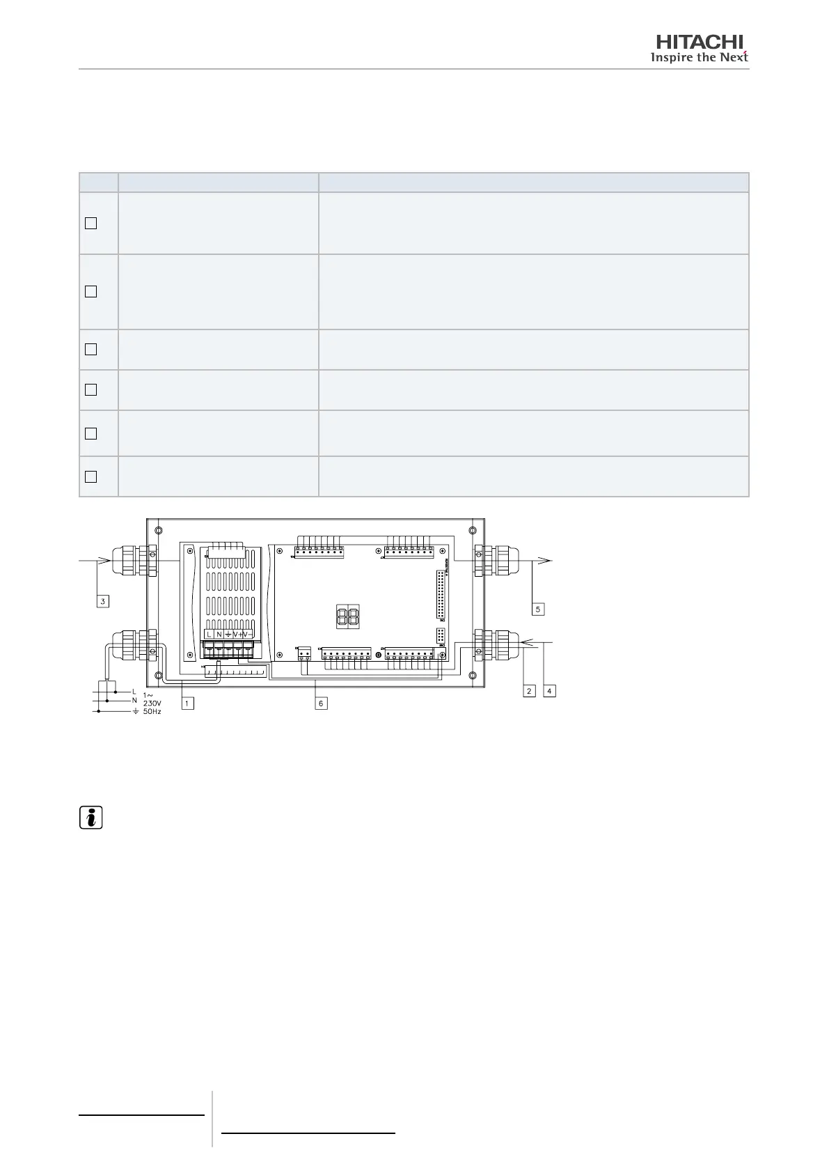
No. Connection Cable Specications
1
Power supply circuit
1~ 230V 50Hz 25W
(With protection circuit)
Select wires accordiong local regulatrions
(Recommended minimum 1.5 mm² H05RN-F)
2
H-LINK
Communication cables for the connection of PC-A1IO to an Hitachi installation, via CS-
NET WEB or any Hitachi unit using same H-LINK terminals.
Twisted pair shielded cable 0.75 mm² H05RN-F.
Shield must be grounded in one side only.
3
DI1~8: Digital input signals
+5V DC. Imax.=0.5 A
Pair cable 0.75 mm² H05RN-F. Use different colour for each cable.
4
AI1~8: Analog input signals
0~5V DC. Imax.= 1.9 A
Pair cable 0.75 mm² H05RN-F. Use different colour for each cable.
5
DO1~8: Output signals (relay)
+5V DC, Imax.= 1.9A
Pair cable 0.75 mm². Use different colour for each cable. Do no apply directly output
signals to the main circuit. Apply some switch, relay or contactor for the correct use
of output signal.
6
PCBs power supply
+5V DC. Imax.= 5 A DC
Pair cable 0.75 mm² H05RN-F.
V:0~5V DC. Imax.= 1.9 A
Field supplied Protections:
CB/EF:5A
ELB: 2 / 40A / 30m A
CB: Circuit Breaker
EF: Electric Fuse
ELB: Earth Leakage Breaker
Checking procedure
Checking of PC-A1IO consist in disconnect and connect the PC-A1IO and check that in the 7-segments display appears
the current software value.
NOTE
Ask your Hitachi distributor what check value has the last version of rmware
8 Control support devices
PC-A1IO
TCGB0106 rev.0 - 12/2014
722
 Loading...


