7 Gateways for building management systems
HARC-BX E
TCGB0106 rev.0 - 12/2014
676676
7.4.4 Test run
1 Check that all the “Wiring connection” and “DIP switch adjustment” procedures have been carried out.
2 Turn the power supply by following the procedure below:
• Plug in the mono bloc air conditioning.
• Plug the HARC-BX E in.
3 Check the HARC-BX E connection.
The 7-segment display will change, as shown in the following table, when the HARC-BX E has been plugged in. Check
the 7-segment display.
Step
7-segment
display
Status
1 - Off
2
88
End of system initialization
3
22
Checking the monobloc air conditioning, number of connected remote controls
4
00
Normal transmission between the HARC-BX E and the monobloc air conditioning.
4 Check the number of identied Indoor Units. The number of Indoor Units identied by the HARC-BX E will be shown
on the 7-segment display after pressing the (PSW [M.CLR]) button on the HARC-BX E. With the 7-segment display
indicating ”00”. (Check if this number is the same as the actual number of Indoor Units).
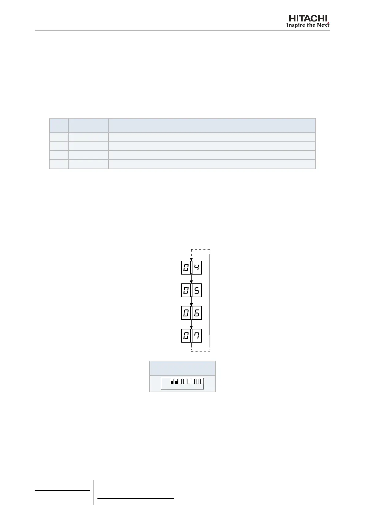
5 When the recognisable indoor units have been located, check the Indoor Unit system numbers and the unit numbers
that the HARC-BX E has identied. Only put the 8 pin DIP switch (201) pin no. 1 in the ON position. All the system and
unit numbers of the recognisable Indoor Units will be shown in the 7-segment display after pressing the (PSW[M.CLR]
button on the HARC-BX E. If multiple Indoor Units are identied, the system and unit numbers for the identied Indoor
Units will be shown sequentially every time the (PSW[CLR]) button is pressed. The system numbers will appear on the
left-hand side of the 7-segment display and the unit numbers on the right-hand side. (Check if this number is the same
as the actual number of Indoor Units).
Outdoor unit
Number
Press M.CLR
Press M.CLR
Press M.CLR
Press M.CLR
Indoor unit
Number
8 pin DIP switch setting
(S202)
 Loading...


