7 Gateways for building management systems
HARC-BX E
TCGB0106 rev.0 - 12/2014
673673
7
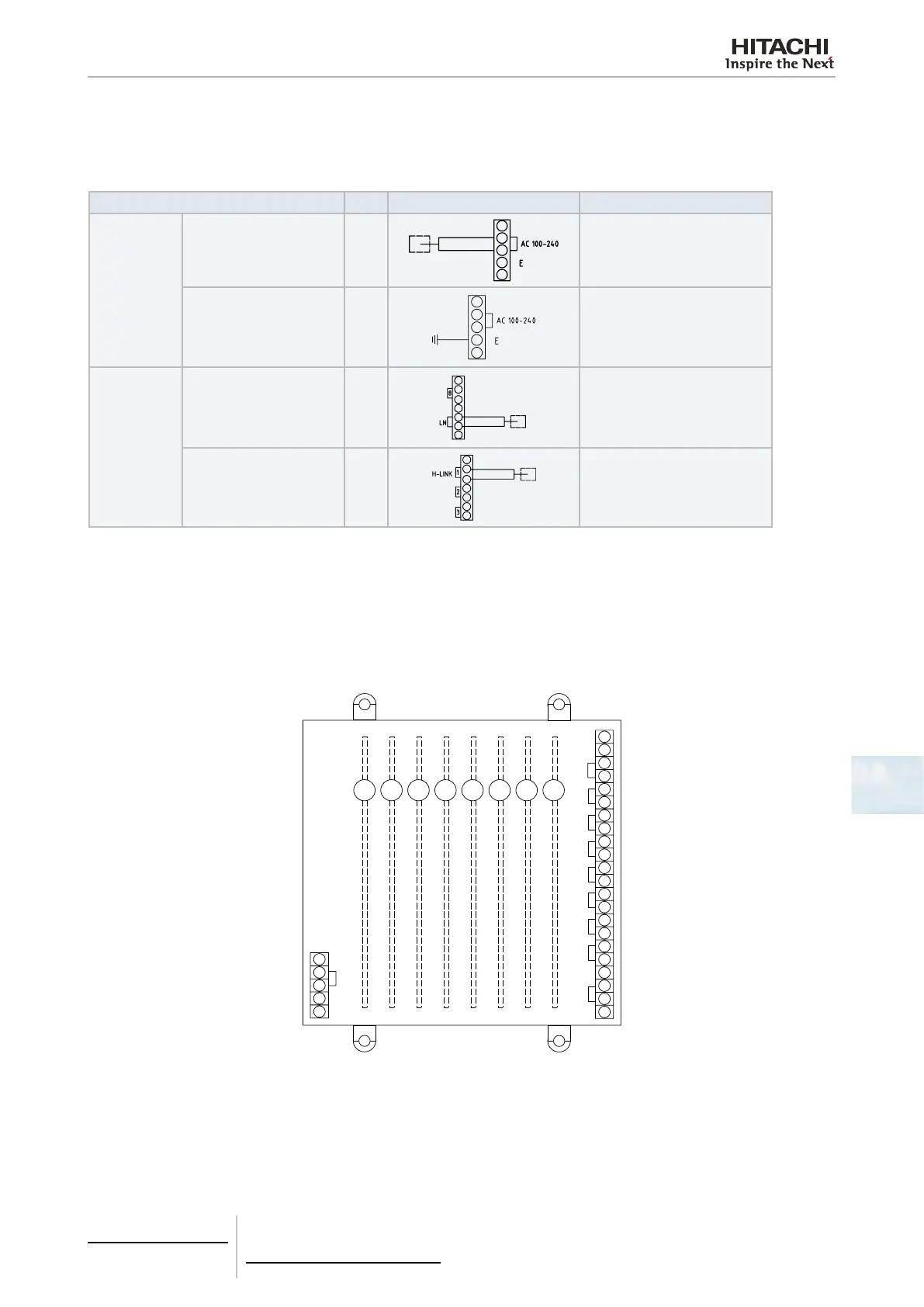
7.4.3.2 Electrical wiring connection
1 Turn off the main electric switch connected to the cable of the HARC-BX E in order to connect the cable.
2 Wire in accordance with the following table.
Section No. * Wiring method Comments
Electric power
line
100/240V HARC-BX E
power supply
-
Earthing wire
-
Control circuit
HARC-BX E upper moni-
toring equipment
Non polar
HARC-BX E
Monobloc air conditioning
Non polar
* “No.” indicates the cable for the "Wiring type”.
7.4.3.3 Installation of the PCB plates and the H-LINK terminals
There are 8 PCBs in each HARC-BX E that correspond to the unit’s H-LINK terminals as shown in the following gure.
So that the PCBs can communicate and control the assigned units, they should be connected to the H-LINK corresponding
to the circuit where the unit is.
AC 100 - 240
1
2
3
4
5
6
7
8
LN
HARC - BX E
H-LINK
1 2 3 4
5
6
7
8
HITACHI BMS Interface

 Loading...


