4 Individual remote controls
PC-ART
TCGB0106 rev.0 - 12/2014
156
(continued from the previous page)
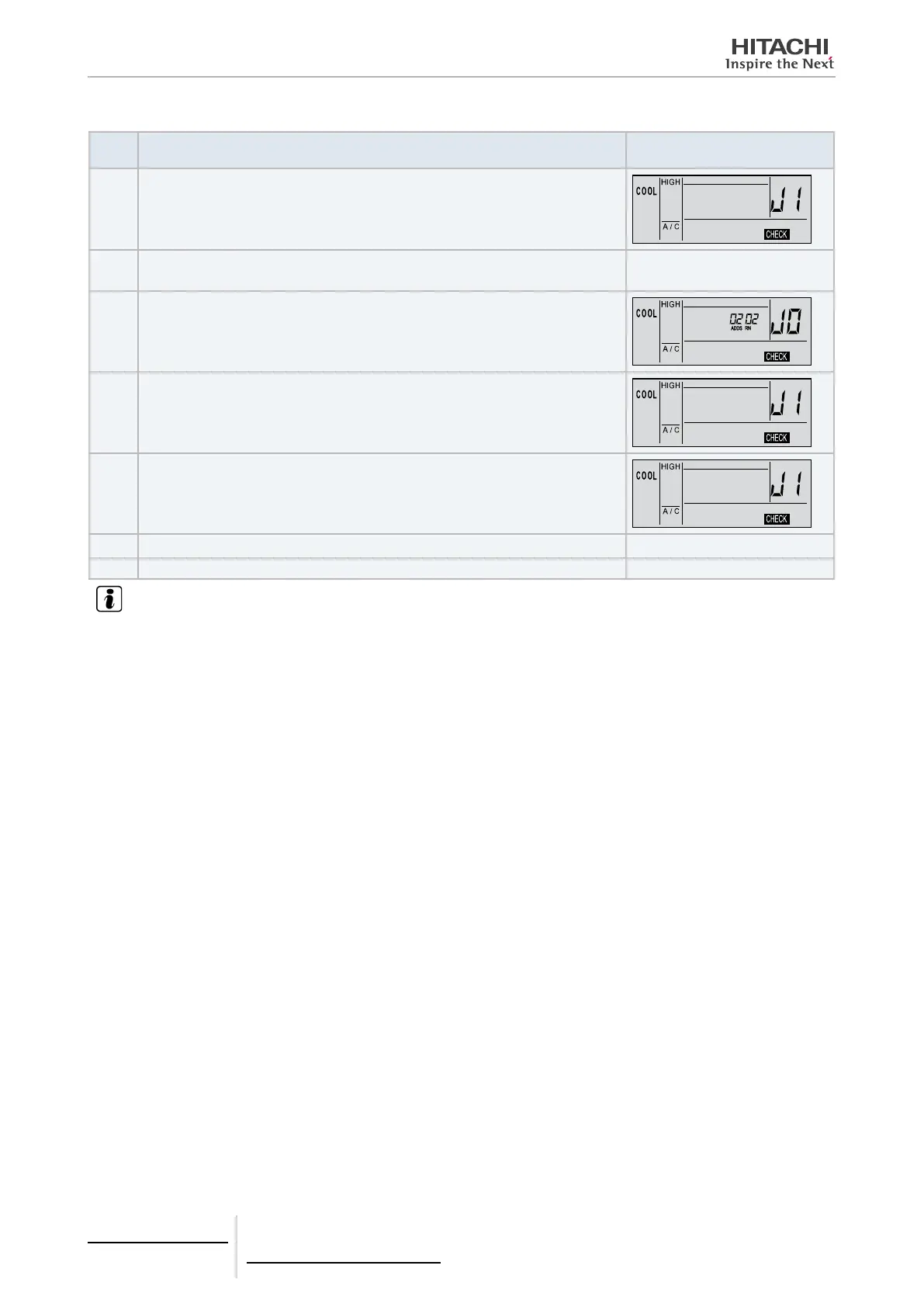
Step
No.
Action required Image
6 Press OK button
7 If there is another unit. Next unit self-check indication.
TEMP
8 e.g.: Indication of unit n° “2”.
:
9 After 7 seconds.
10 From 1 to 5 seconds.
11 After 1 second.
J3 J4 J2
12 Press RESET button Switch off PCB check mode
NOTE
• If this condition persists and alarm code “J1” is not displayed, this means that none of the indoor units have been connected to the
remote control. Check the wiring between the remote control and the indoor unit.
• During this troubleshooting procedure, the following PCB parts cannot be checked.
- Indoor unit PCB: Relay circuit, DIP switch, option circuit, ventilation circuit, protection circuit
- Outdoor unit PCB: Relay circuit, DIP switch, option circuit.
• If this system troubleshooting procedure is run through the central station, the central station indication may change during the
procedure. Please note that this is normal.
• After this troubleshooting procedure is complete, the memory of the meter storing the abnormal conditions described above will
be erased.
To carry out the previous check using a wireless remote control with a receiver built into an indoor wall type unit, use the
following procedure:
1 Switch off the power source.
2 Disconnect connector (CN25) on PWB(M).
3 Connect the PC-ART.
4 Switch on the power.
Once check is complete, switch off the power source again and reconnect the connectors as they were before the check.
 Loading...


