4 Individual remote controls
Receiver kit for wireless remote control
TCGB0106 rev.0 - 12/2014
190
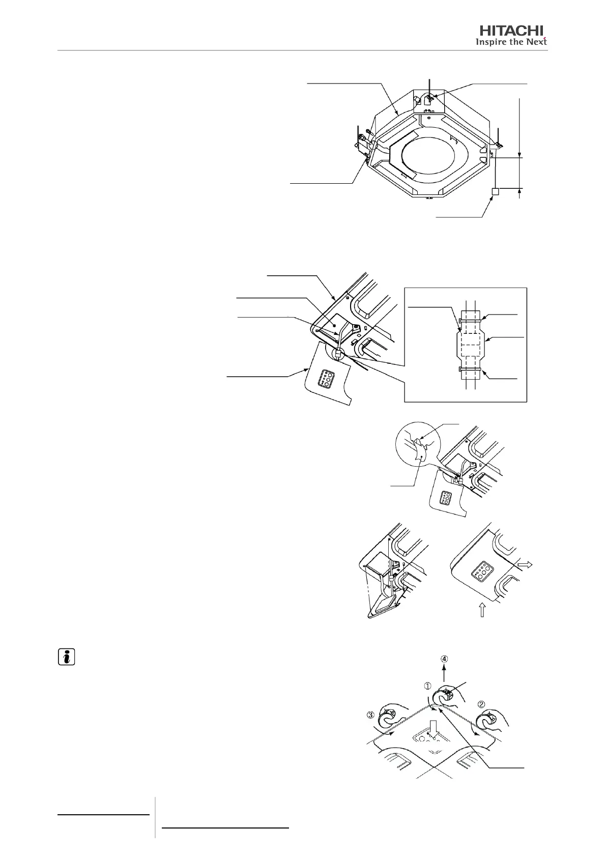
5 Draw the connection cable through the wiring hole
on the indoor unit and pass it over the unit's sus-
pension bracket to the receiver kit installation po-
sition. Secure any excess cable with a cable tie.
Connection cable
Wiring hole of the
indoor unit
Conector
Suspension bracket
100-200 mm
6 Install the air panel accessory on the indoor unit.
7 Connect the receiver kit using the following procedure.
a. Route the connection cable
outside the box and connect it
to the receiver kit cable. Once
connected, cover the connec-
tor with the wiring cover and
secure the cables using a
exible cable tie.
Flexible
cable tie
Wiring
cover
Flexible
cable tie
Connection
cable
Receiver kit
Connection cable
Corner division
Air panel
a. Hook the cable tie onto the air panel ring at the back of the re-
ceiver kit, as shown in the following diagram.
Ring
Flexible
cable tie
a. Hook the L-shaped tab on the back of the receiver kit into the
square hole of the air panel.
8 Hook the other xing tabs (3 positions) into the square holes of the air panel.
NOTE
When removing the receiver kit after installing the air panel:
• The corner point of the receiver kit can be raised by inserting a coin or at-head
screwdriver in the area marked and pressing downwards. With raised, turn
a coin or at-head screwdriver under positions and , and the entire receiver
kit will lift up.
• After disconnecting the xing tabs (3 positions), slide the receiver kit in the direc-
tion of the arrow and remove it.
Coin or at-head screw-
driver
Raise
Area marked

 Loading...


