4 Individual remote controls
Receiver kit for wireless remote control
TCGB0106 rev.0 - 12/2014
206
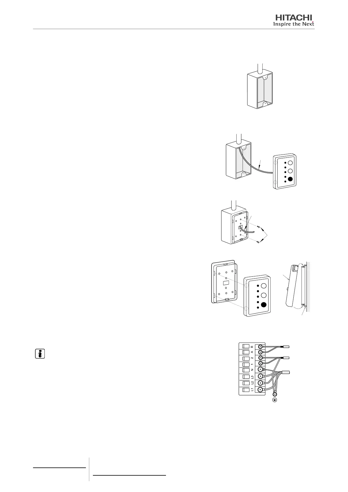
If using an electric control box.
a. There are various types of electrical boxes on the market which
can be used for this installation, for example:
- Electrical box for one remote control unit (without cover.)
- Electrical box for one remote control unit (with cover)
- Output box (with cover)
Also used:
- Rigid metal duct (at least Ø20)
- Screws (M4) (eld supply)
b. Insert the cable into the rigid metal duct.
Cable
c. Mount the wireless receiver kit xing bracket using the screws
supplied by the installer. The diagram shows a switch box for 1
remote control.
Cable
The screws sup-
plied by the in-
staller
d. Fit the cover, making sure not to snag the cable.
Cover
Click sound
Fixing bracket
Hook
6 Remove the cover from the electrical box of the indoor unit and con-
nect the cable to terminals A and B on the terminal plate.
NOTE
If using the RPK model, connect the cable to the CN13 connector (3P blue) on the
PCB of the indoor unit using the cable with connector (factory-supplied with the
RPK).
After connecting the cable, tie any excess cable using a cable tie (factory-sup-
plied) and insert in the electrical control box.
 Loading...


