5 In the case where the multiple centralised ON/OFF controllers are connected in the same H-LINK (Control Line)
system, the group setting is performed in order from the centralised ON/OFF controller No. 0. After completion of the
group setting of the centralised ON/OFF controller No. 0, the group setting of the centralised ON/OFF controller No. 1
is started, and the group setting is continued in order of the number of centralised ON/OFF controller.
I.U.
Add.
Ref.
Add.
0 1 2 3 4 5 6 7 8 9 10 11 12 13 14 15 16 17 18 19 ...
0
G1
G2
Remocon
Group
G3
Remocon Group
G4 G5 G6 G7 G8
1
G9 G10 G11 G12 G13 G14 G15 G16 G1 G2
2
G3 G4 G5 G6 G7 G8 G9 G10
3
4
G1 G2 G3 G4 G5 G6 G7 G8
5
G9 G10 G11 G12 G1 G2 G3 G4 G5 G6
6
G7 G8
...
NOTE
“G1 to G16” indicates the group number set for the centralised ON/OFF controllers
Examples of Group
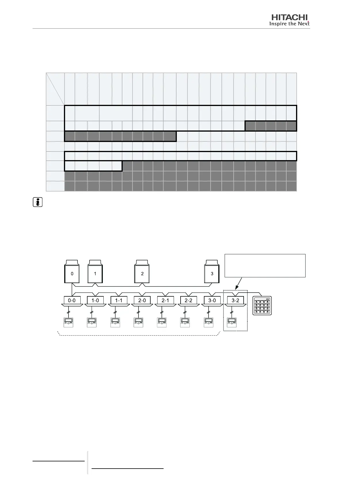
1 In the case where the remote control switch is connected to each indoor unit.
The group setting is not available due
to the inconsecutive indoor unit address
number in the same refrigerant cycle.
Outdoor unit
Indoor unit
Remote
Control
Switch
Nº 0 Central-
ised ON/OFF
Controller
Group 1 Group 2 Group 3 Group 4 Group 5 Group 6 Group 7
Control Range of Nº 0 Centralised ON/OFF Controller
5 Centralised remote controls
PSC-A16RS
TCGB0106 rev.0 - 12/2014
402
 Loading...


