Appendix - Installation of Remote Termination Panels (RTPs) - Analog Input/Digital Input/Digital Output/Analog
Output
222 HC900 Process Controller Installation and User Guide Revision 19
06/14
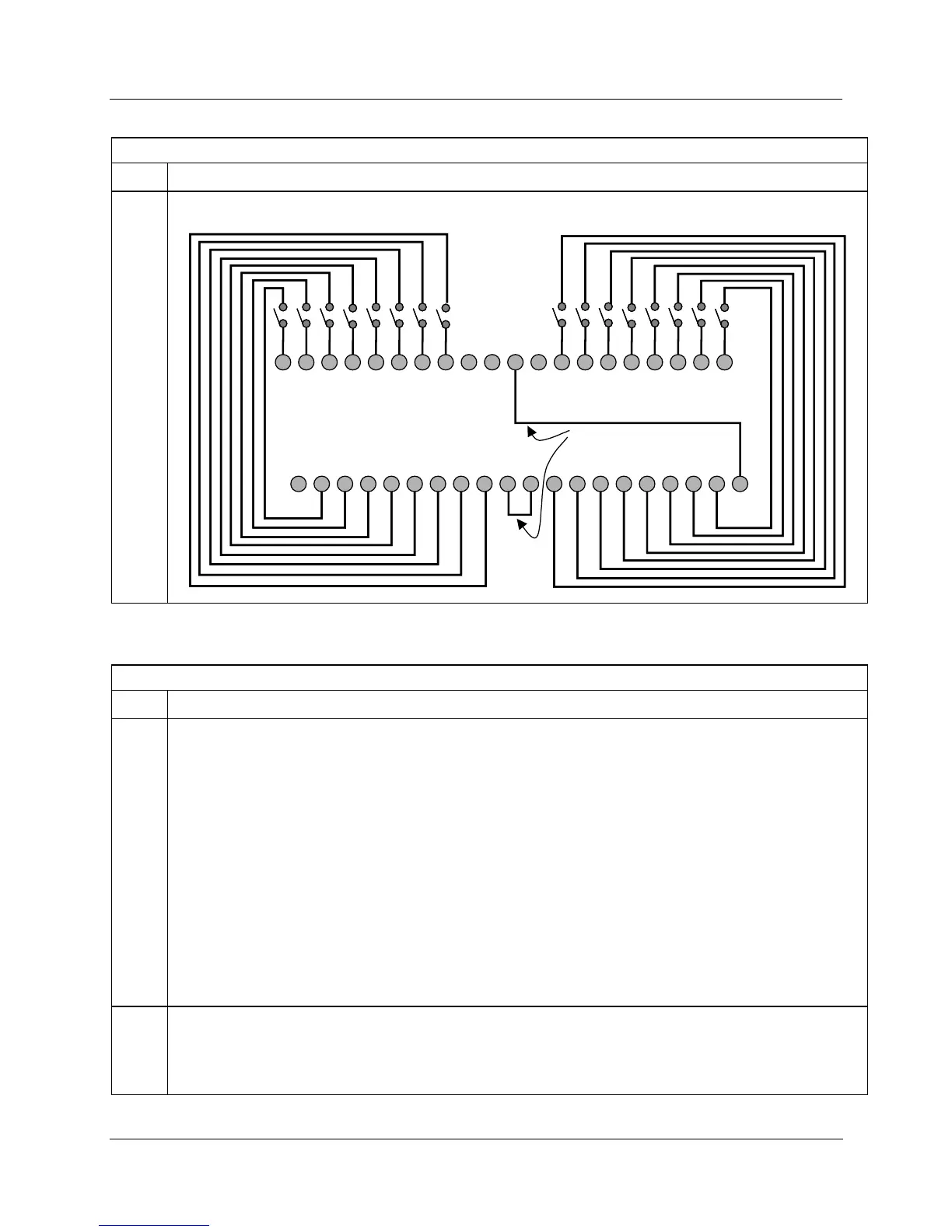
16 Point Contact Digital Input
Step Action
4 Connect field wiring.
1 2 3 4
5 6 7 8 9 10 11 12 13 14 15 16 17 18 19 20
21 22 23 24 25 26 27 28 29 30 31 32 33 34 35
36 37 38 39 40
IN1
IN2
IN3
IN4
IN5
IN6
IN7
IN8
IN9
IN10
IN11
IN12
IN13
IN14
IN15
IN16
IN1+
IN2+
IN9+
IN10+
IN5+
IN6+
COM
IN3+
IN4+
IN7+
IN8+
COM
COM
COM
IN11+
IN12+
IN13+
IN14+
IN15+
IN16+
IN1
-
IN2
-
IN3
-
IN4
-
IN5
-
IN6
-
IN7
-
IN8
-
COM
COM
IN9
-
IN10
-
IN11-
IN12
-
IN13-
IN14
-
IN15-
IN16
-
COM
NA
Install jumper wires
16 Point DC Digital Input
Step Action
1 ATTENTION: RTP and cables are intended for permanent installation within their own enclosure.
ATTENTION: The RTP combines the two groups of 8 inputs into one group of 16.
Mount RTP cable assembly to HC900 Controller (Figure 92).
• Remove appropriate key tabs from terminal board to allow mating with the module. See page 75.
• Connect desired cable to 16 point DC DI module at controller. Choose from:
900RTC-L010 Remote Terminal Low Voltage Cable Assembly, 1.0 meters long
900RTC-L025 Remote Terminal Low Voltage Cable Assembly, 2.5 meters long
900RTC-L050 Remote Terminal Low Voltage Cable Assembly, 5.0 meters long
• Install 16 point DC DI module label into the module connector cover.
• Connect shield drain wire to the grounding bars at the base of the HC900 rack. All field-wiring
shields must be grounded as described in the shield grounding section (page 70).
2 Mount RTP to DIN rail.
• Latch to rail. See page 244.
• Connect cable to RTP.

 Loading...


