I/O Module Installation and Wiring - I/O Module Installation Procedures
Revision 19 HC900 Process Controller Installation and User Guide 75
06/14
Step Procedure Comments Reference
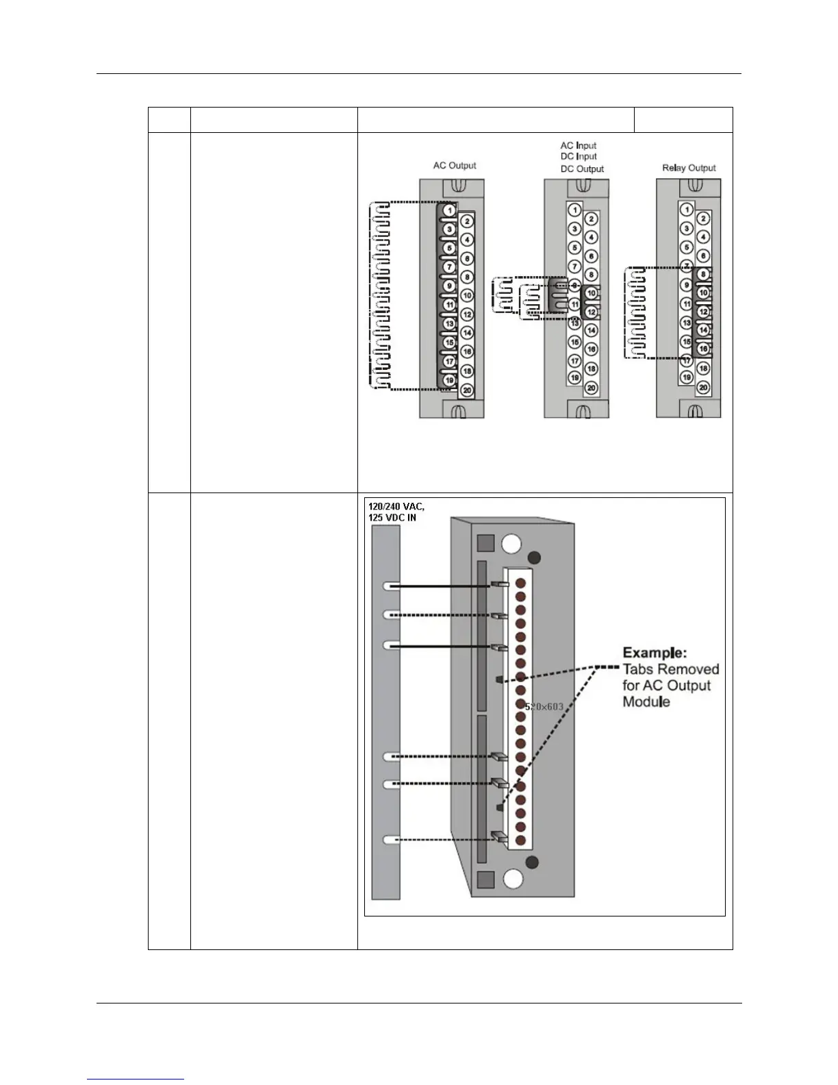
3
(Optional): Install jumper
combs into designated
Barrier style Terminal
Blocks, to reduce the
wiring required to supply
power:
Two-position jumper for
the DC Input Module
and/or on the DC Output
Module.
Ten-position jumper for
the AC Output Module.
Five-position jumper (10-
position jumper cut in half)
for a Relay Output
Module.
Refer to terminal block wiring diagrams for specific information.
4
For each configured and
labeled I/O Module, break
off the "key-tabs" in the
pattern that identifies each
module type.
(For a diagram of each
key-tab pattern, use the
I/O Modules and/or the
diagram shown next page.

 Loading...


