EasyManuals Logo

Honeywell HC900 User Manual

Honeywell HC900
264 pages
To Next Page IconTo Next Page
To Previous Page IconTo Previous Page
Page #88 background imageLoading...
Page #88 background image
I/O Module Installation and Wiring - I/O Module Installation Procedures
76 HC900 Process Controller Installation and User Guide Revision 19
06/14
120/240
VAC,
125VDC
IN
Same as
120/240
Vac IN
Step Procedure Comments Reference
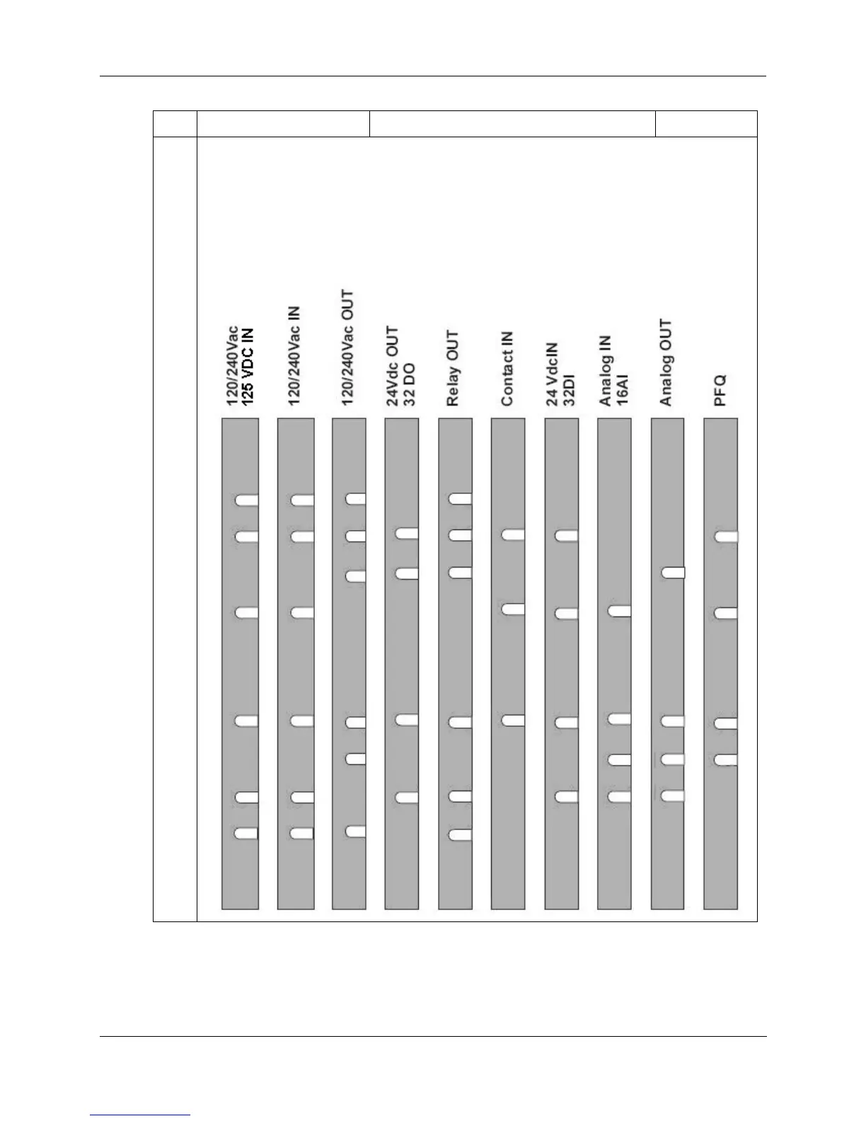
4
contd
NOTE: In the diagram below, the white cut-outs represent the cut-outs on the modules that
accommodate tabs on the Terminal Block. That is, all key-tabs that line up with the white cut-
outs on the diagram should be retained, and all other tabs should be removed.
The orientation of the diagrams below corresponds to the picture of the terminal block, shown in
the previous picture.
Diagrams for I/O Module Key-Tabs

Table of Contents

Other manuals for Honeywell HC900

Questions and Answers:

Question and Answer IconNeed help?

Do you have a question about the Honeywell HC900 and is the answer not in the manual?

Honeywell HC900 Specifications

General IconGeneral
SeriesHC900
RedundancyOptional
Programming LanguageFunction Block Diagram, Ladder Logic, Structured Text
InputsAnalog, Digital
OutputsAnalog, Digital, Relay
DisplayOptional
ControlPID, Advanced Control
Power Supply24V DC or 100-240V AC
Storage Temperature-40°C to 85°C
Humidity5% to 95% non-condensing
Communication ProtocolsModbus, Ethernet

Related product manuals