I/O Module Installation and Wiring - I/O Module Installation Procedures
Revision 19 HC900 Process Controller Installation and User Guide 77
06/14
Step Procedure Comments Reference
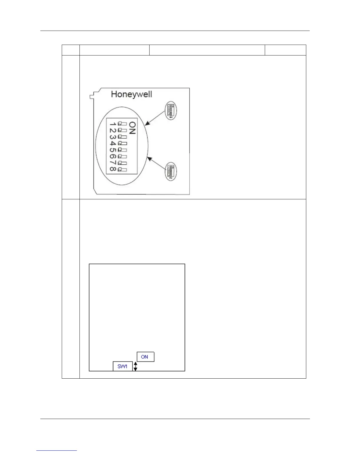
5 If installing High Level 16 channel Analog Input module, set its SW1 and SW2 DIP switches to
ON. This connects an internal 250 ohm resistor.
A small slotted screwdriver or paperclip works well; avoid using pencils.
6 If installing 8- or 16-channel Analog Output module, set its DIP switch as follows. (Switch is
located at edge of module, marked “SW1”.)
• For internal rack power, set DIP switch to ON.
• For external power (18-36V), set DIP switch to OFF (default).
Note: 24VDC external power is required if using 6 or more 8-pt. AO modules or 3 or more 16-pt.
AO modules.
A small slotted screwdriver or paperclip works well; avoid using pencils.

 Loading...


