EasyManuals Logo

Honeywell HC900 User Manual

Honeywell HC900
264 pages
To Next Page IconTo Next Page
To Previous Page IconTo Previous Page
Page #90 background imageLoading...
Page #90 background image
I/O Module Installation and Wiring - I/O Module Installation Procedures
78 HC900 Process Controller Installation and User Guide Revision 19
06/14
Step Procedure Comments Reference
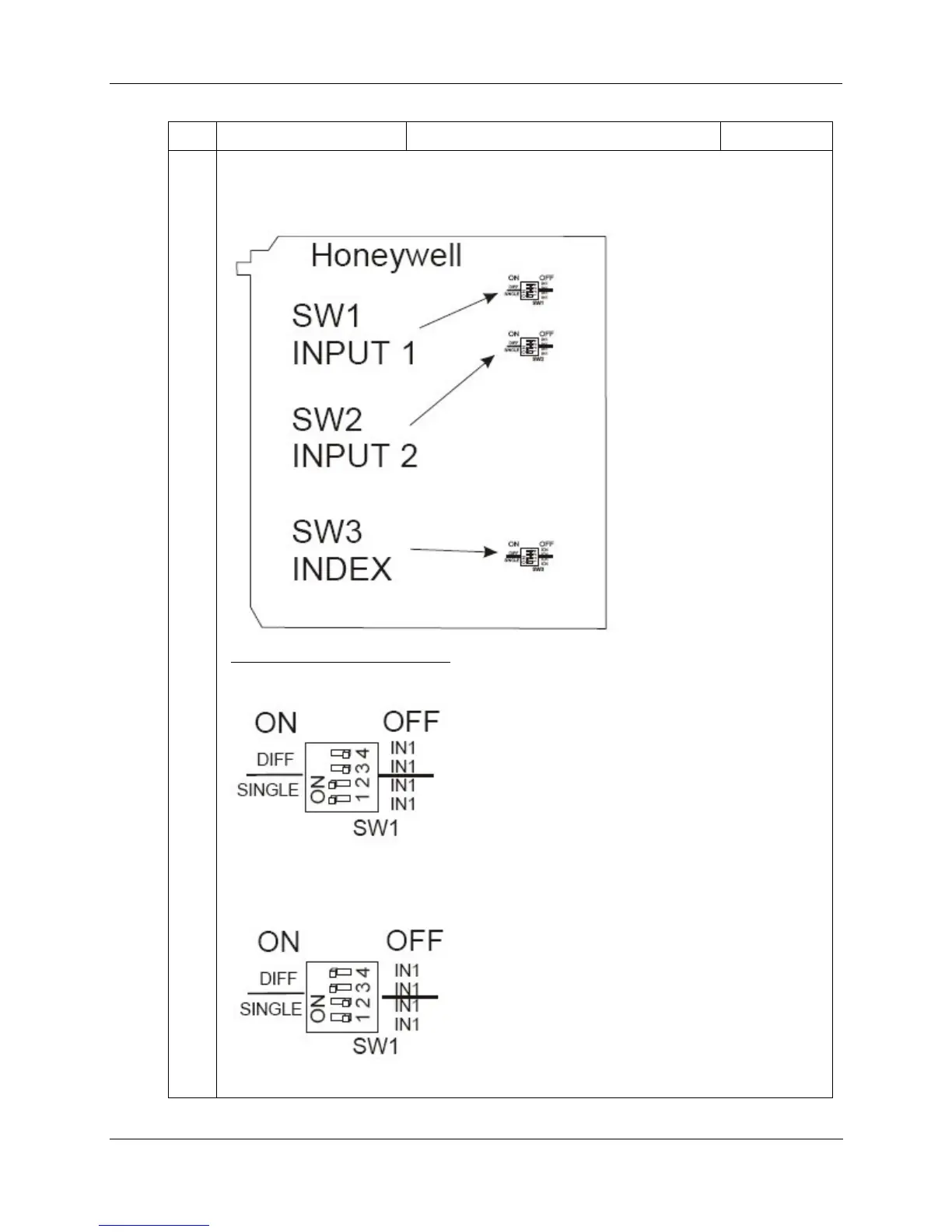
7 If installing a PFQ module, set its Input 1, Input 2 and Index DIP switches to differential or single
ended mode. Inputs mode need not match index mode. See below for switch positions.
Switch location on PFQ module:
Settings (using Input 1 as example)
Single ended (factory setting):
1 and 2 (SINGLE) = ON, 3 and 4 (DIFF) = OFF
Differential:
1 and 2 (SINGLE) = OFF, 3 and 4 (DIFF) = ON

Table of Contents

Other manuals for Honeywell HC900

Questions and Answers:

Question and Answer IconNeed help?

Do you have a question about the Honeywell HC900 and is the answer not in the manual?

Honeywell HC900 Specifications

General IconGeneral
SeriesHC900
RedundancyOptional
Programming LanguageFunction Block Diagram, Ladder Logic, Structured Text
InputsAnalog, Digital
OutputsAnalog, Digital, Relay
DisplayOptional
ControlPID, Advanced Control
Power Supply24V DC or 100-240V AC
Storage Temperature-40°C to 85°C
Humidity5% to 95% non-condensing
Communication ProtocolsModbus, Ethernet

Related product manuals