How the Instrument Works
Standard and Enhanced Trigger Modes
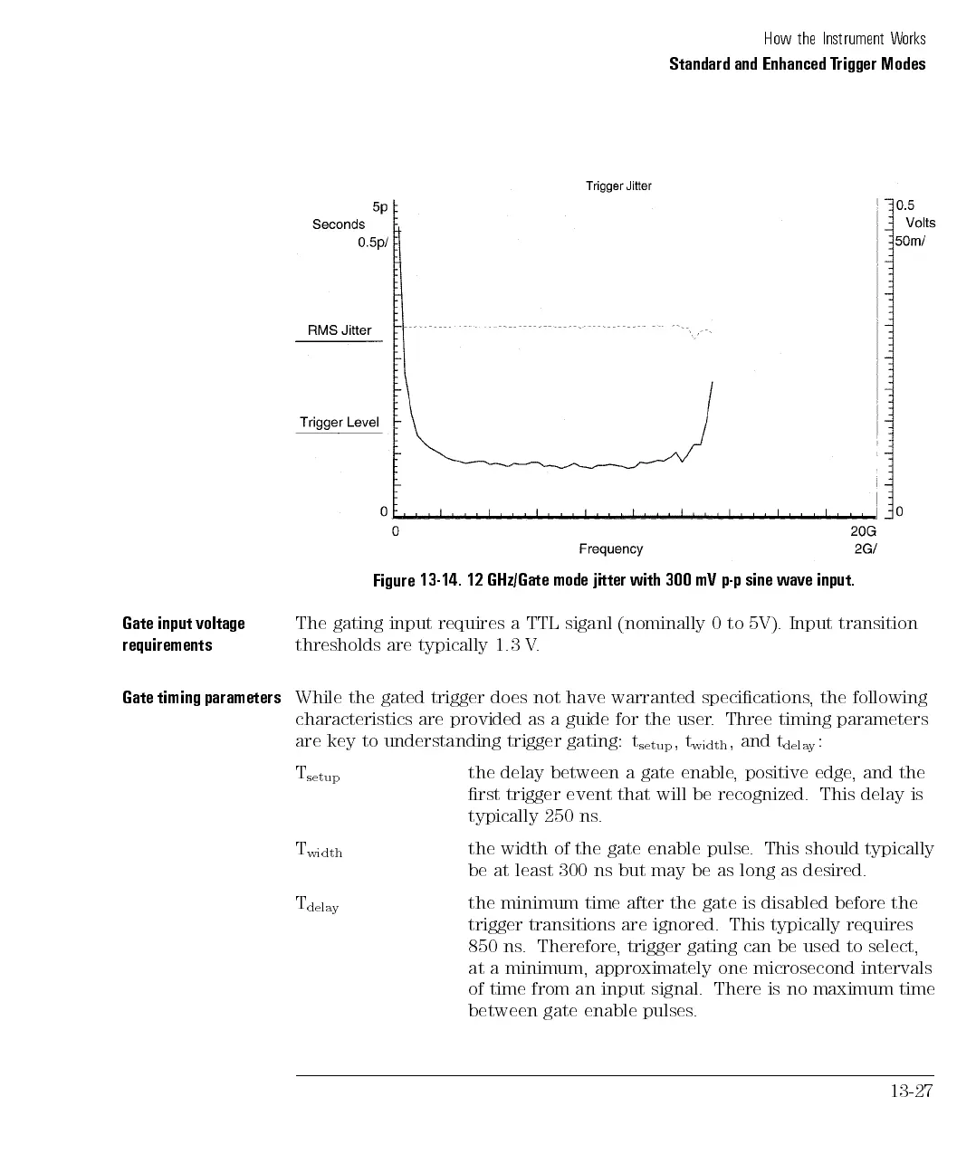
Figure
13-14.
12
GHz/Gate
mode
jitter
with
300
mV
p-p
sine
wave input.
Gate
input
voltage
requirements
The
gating
input
requires
a
TTL
siganl
(nominally
0
to
5V).
Input
transition
thresholds
are
typically
1.3
V
.
Gate
timing
parameters
While
the
gated
trigger
does not
have warranted
specications,
the following
characteristics
are
provided
as
a
guide
for
the user
. Three
timing parameters
are
key
to
understanding
trigger
gating:
t
setup
,
t
width
,
and
t
dela
y
:
T
setup
the delay between a gate enable, positive edge, and the
rst trigger event that will be recognized. This delay is
typically 250 ns.
T
width
the width of the gate enable pulse. This should typically
be
at
least
300
ns
but
may
be
as
long as
desired.
T
dela
y
the
minimum
time
after
the
gate
is
disabled
before
the
trigger transitions are ignored. This typically requires
850 ns. Therefore
, trigger gating can be used to select,
at a minimum, approximately one microsecond intervals
of time from an input signal. There is no maximum
time
between gate enable pulses
.
13-27