• If ISL Trunking is used, group the cables by trunking group. The ports are color-coded to indicate
which ports can be used in the same ISL Trunking group: eight ports marked with solid black ovals
alternate with eight ports marked with oval outlines.
• For easier maintenance, label the fiber optic cables and record the devices to which they are
connected.
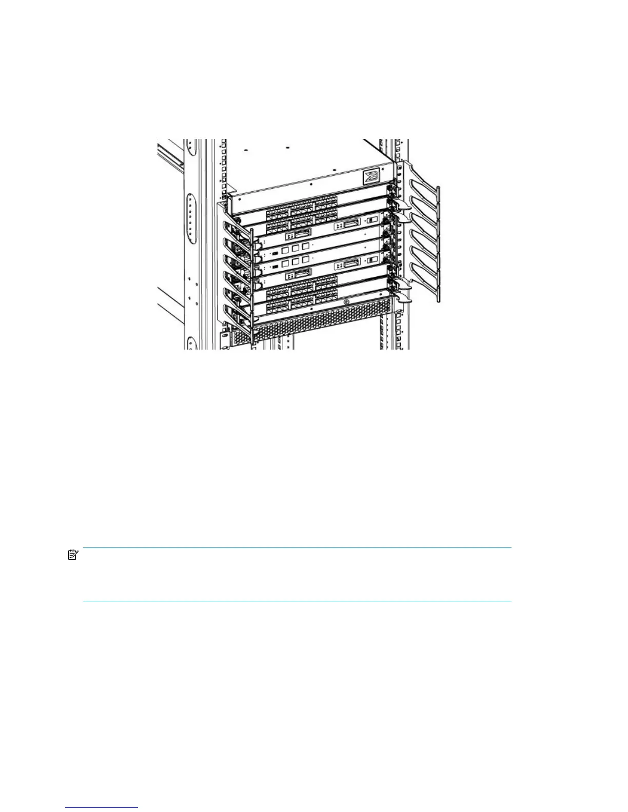
• Route the cables to both the left and right sides of the switch through the cable management fingers.
• Route port cables and other cables away from the LEDs to ensure that the LEDs are visible.
Figure 48 Vertical cable management finger assemblies
Using the optional HP StorageWorks DC SAN Director
Inter-Chassis Link (ICL) cable kit
You can purchase the optional HP StorageWorks DC SAN Director Inter-Chassis Link (ICL) cable kit,
HP part number AK862A. The kit increases the number of ports by interconnecting two DC04 SAN
Director chassis, or a DC04 SAN Director and a DC SAN Director.
The ICL cables and the ICL connectors (see Figure 49) are color-coded and labeled for ease of
installation.
Connect the ICL cables in one of the configurations shown in Figure 50 and Figure 51.
NOTE:
Because the blades in the DC04 SAN Director are installed horizontally, the usual top-to-bottom
orientation becomes a left-to-right orientation.
1. Connect the cables from the left (top) connectors (ICL 1) of the CR4S-8 blades in the first chassis
to the right (bottom) connectors (ICL 0) of the CR4S-8 blades in the second chassis.
DC04 SAN Director Installation140
 Loading...