26399a
1
2
3
4
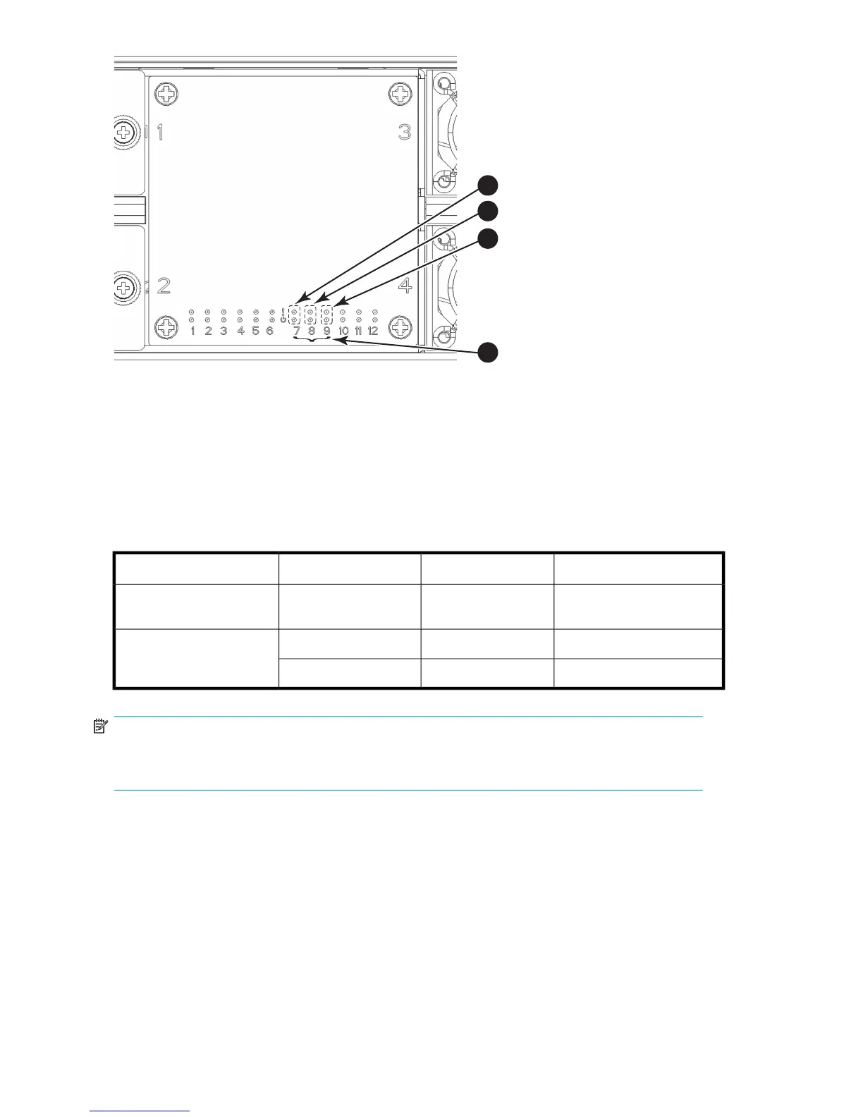
Figure 25 WWN bezel (logo plate)
2. CR blade Status (above) and Power (below) LEDs1. CP blade Status (above) and Power (below) LEDs
4. Slot numbers3. Port blade Status (above) and Power (below) LEDs
Table 15 describes the WWN card LED patterns and the recommended actions for those patterns.
Table 15 WWN bezel LED descriptions
Recommended actionStatusColorLED purpose
No action requiredPower is OK.Steady green
Port blade/CP blade/ CR
blade Power
Check blade.Blade is faulty.Steady amber
Port blade/CP blade/ CR
blade Status
No action requiredBlade is OK.No light (LED is OFF)
NOTE:
If a blade slot or power supply bay has a filler panel installed, the corresponding LEDs on the WWN
blade do not light up.
Monitoring DC SAN Director system components72
 Loading...