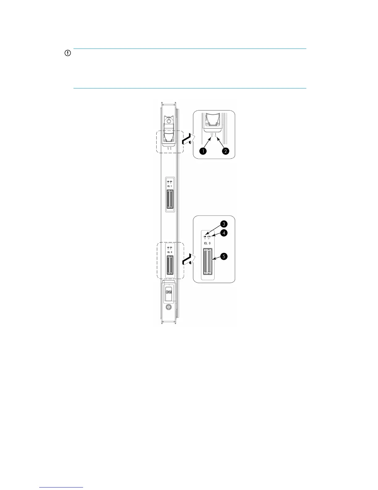
2. Similarly, connect the cables from the right (bottom) connectors (ICL 0) of the CR4S-8 blades in
the first chassis to the left (top) connectors (ICL 1) of the CR4S-8 blades in the second chassis.
IMPORTANT:
The cables can cross between the slot 3 CR4S-8 blade on the first chassis and the slot 6
CR4S-8 blade on the second chassis as long as the left-to-right (top-to-bottom) rule is
followed.
Figure 49 ICL connectors on CR4S-8 blade
2. Power LED1. Status LED
4. ATTN LED3. LINK LED
5. ICL connector
HP StorageWorks DC and DC04 SAN Backbone Director Switches 141
 Loading...