Home
HP
Switch
A7533A - Brocade 4Gb SAN Switch Base
Hardware Reference Guide
Page 61 (FC10-6 Director Blade)
HP A7533A - Brocade 4Gb SAN Switch Base - FC10-6 Director Blade
256 pages
Manual
To Next Page
To Next Page
To Previous Page
To Previous Page
Loading...
25368a
1
2
3
4
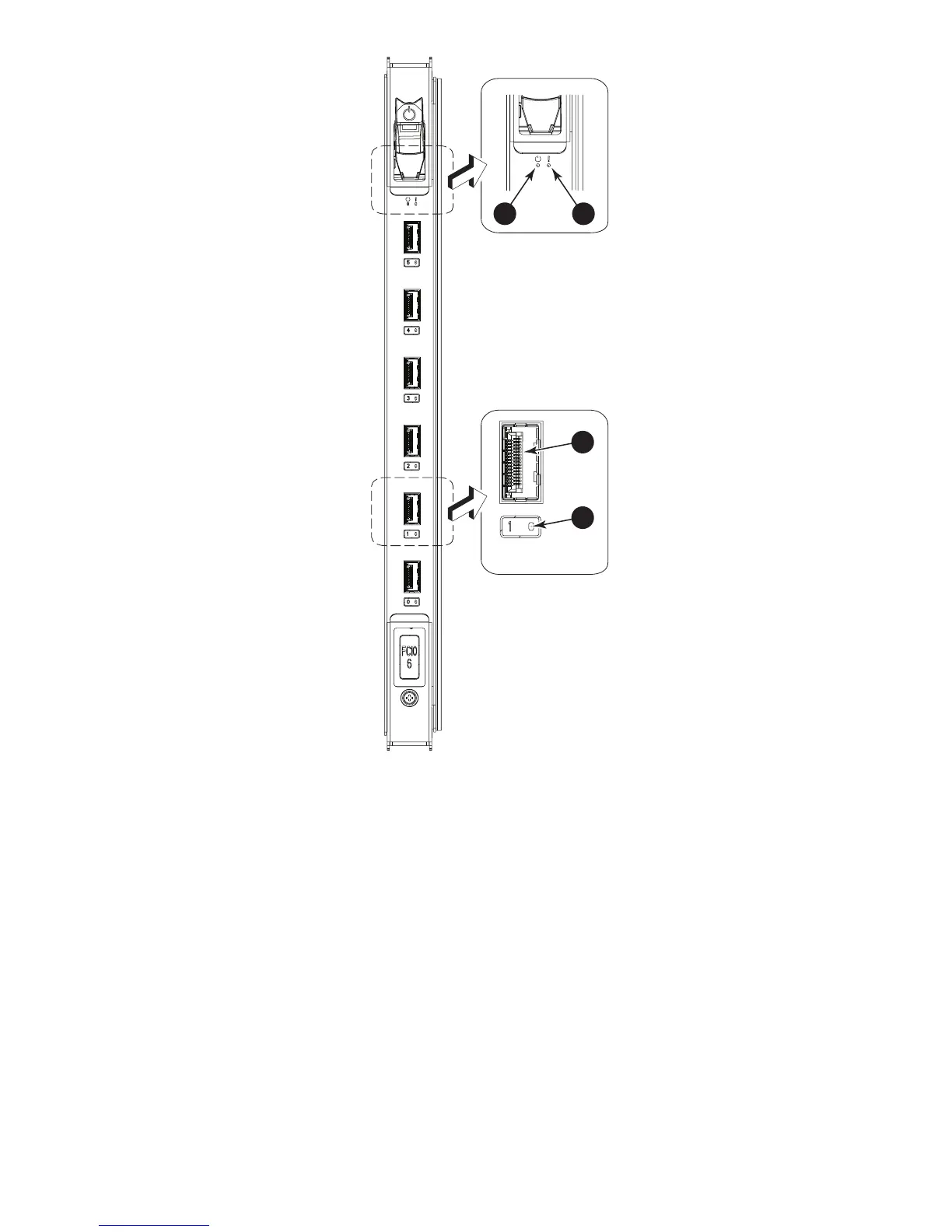
Figur
e 18 FC10
-6 Director blade
2
. Status LED
1. P
ow
er LED
4. P
ort status LED
3
. FC port
2
. Status LED
1. P
ow
er LED
4. P
ort status LED
3
. FC port
HP Stor
age
W
orks DC and DC04 S
AN Backbone Dir
ector S
w
itches
61
60
62
Table of Contents
Main Page
Default Chapter
3
Table of Contents
3
About this Guide
15
Intended Audience
15
Related Documentation
15
Document Conventions and Symbols
16
Document Conventions
16
Rack Stability
17
HP Technical Support
17
Customer Self Repair
17
Subscription Service
17
HP Websites
18
Documentation Feedback
18
HP Storageworks DC SAN Backbone Director Switch Overview
19
HP Storageworks DC SAN Director Power Pack
19
Features
19
Hardware Components
20
Port Side of the DC SAN Director
21
Port Side of the DC SAN Director (Sample Configuration)
21
Non-Port Side of the DC SAN Director
22
Non-Port Side of the DC SAN Director (Sample Configuration)
22
DC SAN Director Blades
23
Blades Available for the DC SAN Director
23
High Availability
24
Reliability
24
Serviceability
24
Software Features
25
Security
25
Security Features
25
Network Manageability
26
Optional Software Licenses
26
DC SAN Director Orderable Software
26
Optional Hardware Kits
27
DC SAN Director Orderable Hardware
27
DC SAN Director Installation
29
Time and Items Required for Installation
29
Installation Tasks, Time and Items Required
29
Site Preparation, Unpacking the DC SAN Director
30
Items Included with the DC SAN Director
32
Installing the DC SAN Director in the 14U Rack Mount Kit
32
DC SAN Director Shipping Carton Contents
32
14U Rack Mount Kit Parts List
33
Items Supplied with the 14U Rack Mount Kit (DC SAN Director)
33
U Rack Mount Kit Contents
34
Attaching the Shelf Brackets
35
Left and Right Shelf Brackets Installed on Rails
36
Shelf Bracket and Clip or Retainer Nut Placement on Cabinet Rails
37
Removing the Chassis Door
38
Installing the Chassis in the Cabinet
38
Positioning the DC SAN Director for Installation in a Cabinet
39
Replacing the Chassis Door
40
Attaching Port Side of Chassis to Rack Rails
40
Aligning the DC SAN Director Door with the Chassis
41
Inserting DC SAN Director Door on Chassis Ball Studs
41
Powering on the DC SAN Director
42
Port Numbering
42
Managing Cables
43
Using the Optional HP Storageworks DC SAN Director Inter-Chassis Link (ICL) Cable Kit
43
ICL Connectors on CR8 Blade
44
Inter-Chassis Link (ICL) Connections (Configuration 1)
45
Inter-Chassis Link (ICL) Connections (Configuration 2)
46
Inter-Chassis Link (ICL) Connections (Configuration 3)
47
Inter-Chassis Link (ICL) Connections (Configuration 4)
48
DC SAN Director Log in and Configuration
49
Configuration Overview
49
Establishing a Serial Connection and Log on to the DC SAN Director
49
Configuring IP Addresses
51
Default IP Addresses and Password
51
Establishing an Ethernet Connection
52
Customizing a Switch Name
53
Setting the Domain ID
53
Verifying the Port Identifier Mode and Connecting to the Fabric
54
Enable Software Licenses
54
Back up the Configuration
55
Monitoring DC SAN Director System Components
57
Introduction
57
Monitoring Director Blade Status
57
FC8-16 Director Blade
58
FC8-32 Director Blade
59
FC8-48 Director Blade
60
FC10-6 Director Blade
61
FR4-18I Director Blade
62
Director Blade LED Descriptions
63
Monitoring Control Processor Blade (CP8) Status
64
Control Processor Blade (CP8)
65
Monitoring Core Switch Blade (CR8) Status
66
CP Blade LED Descriptions
66
Core Switch Blade (CR8)
67
Monitoring Power Supply Status
68
CR Blade LED Descriptions
68
Monitoring Blower Assembly Status
69
Power Supply
69
Power Supply LED Descriptions
69
Blower Assembly
70
Blower Assembly LED Descriptions
70
Monitoring WWN Bezel (Logo Plate) and WWN Card Status
71
Messages that May Indicate WWN Card Failure
71
WWN Bezel (Logo Plate)
72
WWN Bezel LED Descriptions
72
Replacing DC SAN Director Field-Replaceable Units (Frus)
73
Replacing the Chassis Door
73
Removing the Chassis Door
73
Installing the Chassis Door
74
Replacing the Cable Management Comb
74
Removing a Cable Management Comb
74
Removing or Replacing a Chassis Door
74
Installing a Cable Management Comb
75
Replacing a Director Blade
75
Removing or Replacing the Cable Management Comb
75
Removing a Director Blade
76
Installing a Director Blade
77
Director Blade (FC8-48 Shown)
77
Replacing a Director Blade Filler Panel
78
Removing a Filler Panel
78
Installing a Filler Panel
79
Replacing a Control Processor Blade (CP8)
79
Director Blade Filler Panel
79
How to Determine Whether or Not to Replace a CP Blade
80
Recording Critical DC SAN Director Information
80
Removing a Control Processor Blade (CP8)
82
Installing a Control Processor Blade (CP8)
83
Control Processor Blade (CP8)
83
Verifying Operation of the New CP Blade
84
Replacing a Core Switch Blade (CR8)
86
How to Determine Whether or Not to Replace a CP Blade
86
Removing a Core Switch Blade (CR8)
86
Installing a Core Switch Blade (CR8)
87
Core Switch Blade (CR8)
87
Replacing a Power Supply
88
Removing a Power Supply
88
Installing a Power Supply
88
Replacing a Blower Assembly
89
Removing a Blower Assembly
89
Power Supply
89
Installing a Blower Assembly
90
Replacing the WWN Bezel (Logo Plate) and WWN Card
91
How to Determine Whether or Not to Replace a WWN Card
91
Blower Assembly
91
WWN LED Patterns
92
Commands Identifying the WWN Card Status
92
Removing the WWN Bezel (Logo Plate) and WWN Card
93
WWN Card Related System Log Messages
93
Installing the WWN Bezel (Logo Plate) and WWN Card
95
WWN Bezel (Logo Plate) and WWN Card
95
Replacing Sfps and Xfps
96
Replacing the DC SAN Director Chassis
97
Optical Transceiver (SFP and XFP) Extraction Tool
97
Verifying the Need for Replacing the Chassis
98
Recording Critical DC SAN Director and SAN Information
98
Critical Information Checklist
98
Disconnecting from the Network and the Fabric
102
Removing Components from the Chassis
103
Installing the Replacement Chassis
103
Installing Components into the New Chassis
104
Configuring the New Chassis Serial Number
104
Verifying that the System Is Operating Correctly
105
Reconnecting to the Network and the Fabric
108
Verifying that the Configuration of the Fabric Is Correct
108
Cable Routing Table
110
Cable Routing Table for DC SAN Director (48 Ports Shown)
110
HP Storageworks DC04 SAN Backbone Director Switch Overview
113
HP Storageworks DC04 SAN Backbone Director Switch
113
Features
113
Hardware Components
114
Port Side of the DC04 SAN Director
115
Port Side of the DC04 SAN Director (Sample Configuration)
116
Port Side of the DC04 SAN Director with the Port Side Exhaust Kit Installed
116
Non-Port Side of the DC04 SAN Director
117
Non-Port Side of the DC04 SAN Director (Sample Configuration)
117
DC04 SAN Director Blades
118
Blades Available for the DC04 SAN Director
118
High Availability
119
Reliability
119
Serviceability
120
Software Features
120
Security
121
Network Manageability
121
Security Features
121
Optional Software Licenses
122
DC04 SAN Director Orderable Software
122
Optional Hardware Kits
123
DC04 SAN Director Orderable Hardware
123
DC04 SAN Director Installation
125
Time and Items Required for Installation
125
Installation Tasks, Time and Items Required
125
Site Preparation, Unpacking the DC04 SAN Director
126
Items Included with the DC04 SAN Director
128
Installing the DC04 SAN Director in a Rack
128
DC04 SAN Director Shipping Carton Contents
128
Rack Mount Kit Contents
129
Torque Requirements
130
Rack Mount Kit Hardware
130
Installing the Cabinet Hardware
131
Clip and Retainer Nut Locations on Cabinet Rails
132
Installing the Shelf in the Cabinet
133
Installing the Air-Duct Assembly
133
Installing the DC04 SAN Director in the Cabinet
134
Securing the Top-Rail Assembly in the Cabinet
134
Installing the DC04 SAN Director in the Cabinet
135
Installing the DC04 SAN Director Shipping Brackets
136
Cabinet Rail-To-Rail Depths
136
DC04 SAN Director Shipping Brackets (Left Side)
137
Installing the Shipping Brackets on the DC04 SAN Director
137
Powering on the DC04 SAN Director
138
Installing the DC04 SAN Director with Shipping Brackets
138
Port Numbering
139
Managing Cables
139
Using the Optional HP Storageworks DC SAN Director Inter-Chassis Link (ICL) Cable Kit
140
Vertical Cable Management Finger Assemblies
140
ICL Connectors on CR4S-8 Blade
141
DC04 SAN Director ICL Cabling
142
DC04 SAN Director to DC SAN Director ICL Cabling
143
DC04 SAN Director Log in and Configuration
145
Configuration Overview
145
Establishing a Serial Connection and Logging on to the DC04 SAN Director
145
Configuring IP Addresses
147
Default IP Addresses and Password
147
Establishing an Ethernet Connection
148
Customizing a Switch Name
149
Setting the Domain ID
149
Setting the Date and Time
150
Setting the Date
150
Setting the Time Zone
150
Synchronizing Local Time
151
Verifying the Port Identifier Mode and Connecting to the Fabric
151
Enabling Software Licenses
152
Backing up the Configuration
152
Monitoring DC04 SAN Director System Components
153
Introduction
153
Monitoring Director Blade Status
153
FC8-16 Director Blade
154
FC8-32 Director Blade
155
FC8-48 Director Blade
156
FC10-6 Director Blade
157
FR4-18I Router Blade
158
Director and Application Blade LED Descriptions
159
Monitoring Control Processor Blade (CP8) Status
160
Control Processor Blade (CP8)
161
Monitoring Core Switch Blade (CR4S-8) Status
162
CP8 Blade LED Descriptions
162
Core Switch Blade (CR4S-8)
163
Monitoring Power Supply Status
164
CR4S-8 Blade LED Descriptions
164
Monitoring Blower Assembly Status
165
Power Supply
165
Power Supply LED Descriptions
165
Blower Assembly
166
Blower Assembly LED Descriptions
166
Monitoring WWN Bezel (Logo Plate) and WWN Card Status
167
Messages that May Indicate WWN Card Failure
167
WWN Bezel (Logo Plate)
168
Replacing DC04 SAN Director Field-Replaceable Units (Frus)
169
Replacing the Chassis Door
169
Removing the Chassis Door
169
Installing the Chassis Door
170
Replacing the Vertical Cable Management Assembly
170
Removing a Cable Management Finger Assembly
170
Removing or Replacing a Chassis Door
170
Installing a Cable Management Finger Assembly
171
Replacing DC04 SAN Director Port and Application Blades
171
Removing or Replacing the Cable Management Finger Assembly
171
Removing a Blade
172
Installing a Blade
173
DC04 SAN Director Blade (FC8-48 Shown)
173
Replacing a Blade Filler Panel
174
Removing a Filler Panel
174
Installing a Filler Panel
174
Replacing a Control Processor Blade (CP8)
175
DC04 SAN Director Blade Filler Panel
175
How to Determine Whether or Not to Replace a CP Blade
176
Recording Critical DC04 SAN Director Information
176
Removing a Control Processor Blade (CP8)
178
Installing a Control Processor Blade (CP8)
179
Control Processor Blade (CP8)
179
Verifying Operation of the New CP Blade
180
Replacing a Core Switch Blade (CR4S-8)
181
How to Determine Whether or Not to Replace a Core Switch Blade
182
Removing a Core Switch Blade
182
Installing a Core Switch Blade
183
Core Switch Blade (CR4S-8)
183
Replacing a Power Supply
184
Removing a Power Supply
184
Installing a Power Supply
184
Power Supply Identification
184
Replacing a Blower Assembly
185
Power Supply
185
Removing a Blower Assembly
186
Installing a Blower Assembly
186
Replacing the WWN Bezel (Logo Plate) and WWN Card
187
How to Determine Whether or Not to Replace a WWN Card
187
Blower Assembly
187
WWN LED Patterns
188
Commands Identifying the WWN Card Status
188
Removing the WWN Bezel (Logo Plate) and WWN Card
189
WWN Card Related System Log Messages
189
Installing the WWN Bezel (Logo Plate) and WWN Card
191
WWN Bezel (Logo Plate) and WWN Card
191
Replacing Sfps and Xfps
192
Replacing the DC04 SAN Director Chassis
193
Optical Transceiver (SFP and XFP) Extraction Tool
193
Verifying the Need for Replacing the Chassis
194
Recording Critical DC04 SAN Director and SAN Information
194
Critical Information Checklist
194
Disconnecting from the Network and the Fabric
198
Removing Components from the Chassis
199
Installing the Replacement Chassis
199
Installing Components into the New Chassis
200
Configuring the New Chassis Serial Number
200
Verifying that the System Is Operating Correctly
201
Reconnecting to the Network and the Fabric
203
Verifying that the Configuration of the Fabric Is Correct
205
Cable Routing Table
206
Cable Routing Table for DC04 SAN Director (48 Ports Shown)
206
A Technical Specifications
209
General Specifications
209
Power Cords
209
System Architecture
210
DC SAN Director System Architecture
210
DC04 SAN Director System Architecture
212
System Size and Weight
213
DC SAN Director System Size and Weight
213
DC04 SAN Director System Size and Weight
213
System Blade and FRU Weights
214
Facility Requirements
214
System FRU Weights
214
Power Specifications
215
DC SAN Director
215
DC04 SAN Director
215
DC SAN Director Power Specifications
215
Power Cords
216
DC04 SAN Director Power Specifications
216
Power Cords (Japan, Denan)
219
Environmental Requirements
219
DC SAN Director Environmental Requirements
219
Fibre Channel Port Specifications
220
DC04 SAN Director Environmental Requirements
220
Data Transmission Ranges
222
Supported Cable Speeds and Distances
222
B Intelligent Blades
223
B-Series MP Router Blade (FR4-18I) Overview
223
Items Included with the FR4-18I Blade
223
Optional Items
224
Installing and Configuring the FR4-18I Blade
224
Installing the FR4-18I Blade in the Director
224
B-Series MP Router Blade (FR4-18I) Components
225
Configuring FCIP and Fibre Channel Routing Services and Enable the Ports
226
Cabling the FR4-18I Blade
226
Recommendations for Cable Management
227
C Regulatory Compliance and Safety Notices
229
Regulatory Compliance Notices
229
Federal Communications Commission Notice for Class a Equipment
229
Modifications
229
Cables
229
Regulatory Compliance Identification Numbers
229
Laser Device
230
Laser Safety Warning
230
Certification and Classification Information
230
Laser Product Label
231
International Notices and Statements
231
Canadian Notice (Avis Canadien)
231
Class a Equipment
231
European Union Regulatory Notice
231
Class 1 Laser Product Label
231
Japanese Notice
232
Korean Notices
232
Korean Notice
232
Environmental Regulation Compliance
233
China Rohs
233
Environmental Protection Use Period (EPUP) Disclaimer
233
TS/HS Dual Language Sheet
233
Hazardous Substances
233
Safety Guidelines
235
Electrostatic Discharge Recommendations
235
Grounding Methods
236
Battery Replacement Notice
236
Taiwan Battery Recycling Notice
237
Power Cords
237
Japanese Power Cord Notice
237
D Port Numbering Templates
239
HP Storageworks DC SAN Backbone Director Switch Templates
239
Port Side Populated with Eight FC8-48 Port Blades, Two CR8 Blades, and Two CP8
240
Port Side Populated with Eight FC8-32 Port Blades, Two CR8 Blades, and Two CP8
241
Port Side Populated with Eight FC8-16 Port Blades, Two CR8 Blades, and Two CP8
242
FC10-6 Port Blades
243
FR4-18I Router Blade
244
HP Storageworks DC04 SAN Backbone Director Switch Templates
245
Port Side Populated with Four FC8-48 Port Blades, Two CR4S-8 Blades, and Two CP8 Blades
246
Port Side Populated with Four FC8-32 Port Blades, Two CR4S-8 Blades, and Two CP8 Blades
247
Port Side Populated with Four FC8-16 Port Blades, Two CR4S-8 Blades, and Two CP8 Blades
248
FC10-6 Port Blades
249
FR4-18I Router Blades
250
Index
251
Other manuals for HP A7533A - Brocade 4Gb SAN Switch Base
User Guide
248 pages
Administrator's Guide
576 pages
Release Note
76 pages
Manual
29 pages
Related product manuals
HP Brocade 8Gb
64 pages
HP A7503
63 pages
HP A7510
63 pages
HP AF620A
12 pages
HP A5800-48G
36 pages
HP Aruba JL253A
775 pages
HP A5120 Series
55 pages
HP Aruba JL255A
775 pages
HP A5820X Series
146 pages
HP A5500 HI Series
62 pages
HP Aruba 8325 Series
70 pages
HP Aruba 3810M Series
102 pages