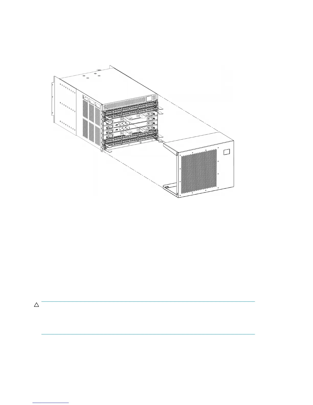
Installing the chassis door
To install the chassis door (see Figure 63 on page 170):
1. Align the holes in the door with the pins in the chassis
2. Push the door into place.
Figure 63 Removing or replacing a chassis door
Replacing the vertical cable management assembly
The DC04 SAN Director is equipped with two vertical cable management finger assemblies. It can
continue to operate during the replacement of the cable management fingers. Due to the horizontal
orientation of the blades in the DC04 SAN Director, the finger assemblies are attached to the uprights
of the mounting rack.
The replacement procedure for the vertical cable management fingers takes less than five minutes.
You will need a #1 Phillips screwdriver.
Removing a cable management finger assembly
CAUTION:
Wear a grounded ESD strap when handling DC04 SAN Director components. The DC04 SAN Director
chassis provides a grounding connection above the power connectors. Also, store ESD-sensitive
components in antistatic packaging.
To remove the cable management comb:
1. Rearrange the cables around one of the cable management finger assemblies.
Replacing DC04 SAN Director field-replaceable units (FRUs)170
 Loading...