124 Powermax125 Service Manual 808070
8 – Troubleshooting and System Tests
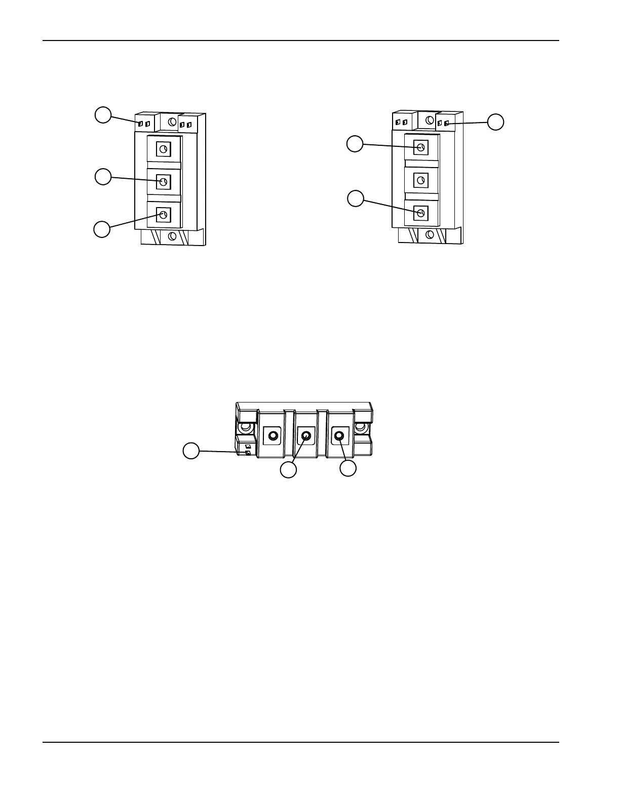
Figure 11 – IGBT, inverter tests
Figure 12 – IGBT, pilot arc
1 Yellow lead Gate (“G2” or “6”)
2 Black lead Emitter (“E2” or “2”)
3 Red lead Collector (“C2E1” or “1”)
4 Red lead Collector (“C1” or “3”)
5 Black lead Emitter (“C2E1” or “1”)
6 Yellow lead Gate (“G1” or “4”)
1 Yellow lead Gate 2 (“G2” or “6”)
2 Black lead Emitter 2 (“E2” or “2”)
3 Red lead Collector 2 (“C2” or “1”)