EasyManuals Logo

Hypertherm Powermax 125 Service Manual

Hypertherm Powermax 125
317 pages
To Next Page IconTo Next Page
To Previous Page IconTo Previous Page
Page #187 background imageLoading...
Page #187 background image
Powermax125 Service Manual 808070 187
9 Power Supply Component Replacement
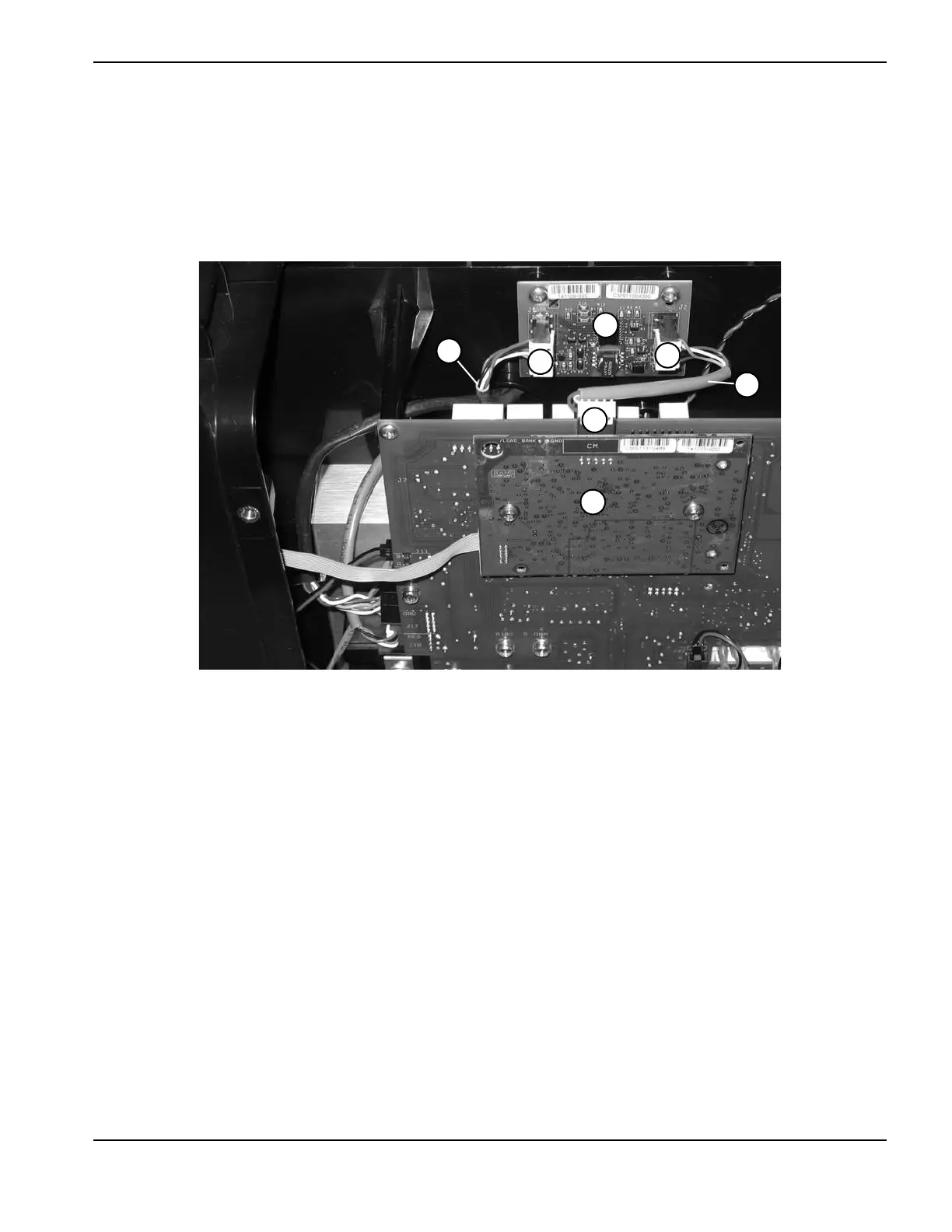
13. Push the connector from the long RS-485 cable onto the J1 connector of the RS-485 board.
14. On the short RS-485 cable, push the connector with the smaller white dust cover onto the J7 connector of the
DSP board.
15. Push the other connector onto the J2 connector of the RS-485 board.
Figure 58
16. Complete the following procedures:
a. See Install the end panel bracket on page 175.
b. See Install the component barrier on page 173.
c. See Install the power supply cover on page 172.
d. Reconnect the power and gas supply.
4
5
2
1
3
6
7
1 J1 connector
2 Long RS-485 cable
3 DSP board
4 J7 connector
5 Short RS-485 cable
6 J2 connector
7 RS-485 board

Table of Contents

Other manuals for Hypertherm Powermax 125

Questions and Answers:

Question and Answer IconNeed help?

Do you have a question about the Hypertherm Powermax 125 and is the answer not in the manual?

Hypertherm Powermax 125 Specifications

General IconGeneral
Output Current30-125 A
Input Power15.2 kW
Open Circuit Voltage300 VDC
Gas SupplyClean, dry, oil-free air or nitrogen
Input Power Cable Length10 ft (3 m)
Rated Output Current125 A
Gas TypeAir or nitrogen
Cutting Capacity1-1/4 inch (32 mm)
Pierce Capacity1 inch (25 mm)
Input Voltage200-600 V, 3-PH
Duty Cycle100% @ 125 A
CertificationsCSA
Maximum Clean Cut Thickness1-1/4 inch (32 mm)
Cooling MethodFan-cooled
Torch OptionsHand

Related product manuals