EasyManuals Logo

Hypertherm Powermax 125 Service Manual

Hypertherm Powermax 125
317 pages
To Next Page IconTo Next Page
To Previous Page IconTo Previous Page
Page #186 background imageLoading...
Page #186 background image
186 Powermax125 Service Manual 808070
9 Power Supply Component Replacement
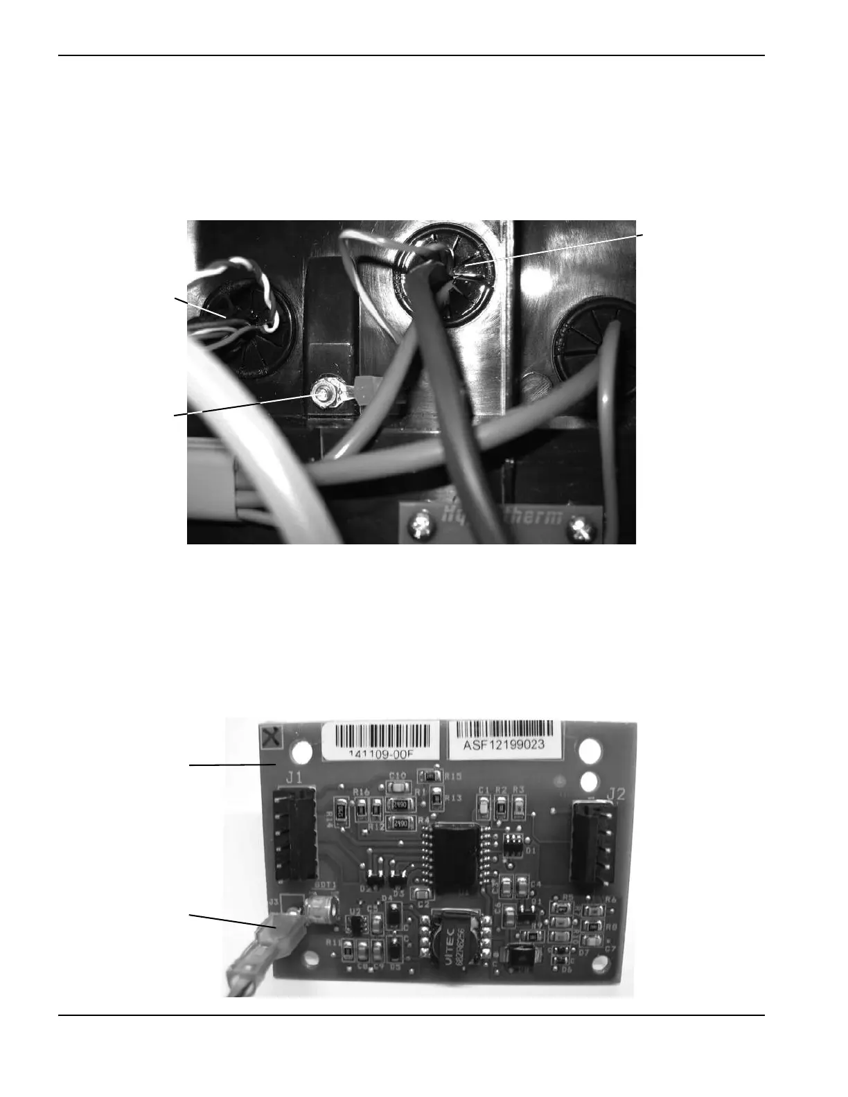
9. Attach the green/yellow ground wire ring connector to the threaded post located between the center and left
grommets. (See Figure 56.) Tighten the supplied nut onto the threaded post to 17.3 kg-cm (15 inch-pounds).
10. Push the ground wire connector through the center grommet.
Figure 56
11. From the power board side of the power supply, secure the RS-485 board to the plastic mounting posts located on
the center panel directly behind the DSP board. Tighten the 2 supplied screws to 11.5 kg-cm (10 inch-pounds). See
Figure 58 on page 187.
12. Attach the ground wire connector to the bottom left connector on the RS-485 board.
Figure 57
Left grommet
Ground wire
Center grommet
RS-485 board
Ground wire
connector

Table of Contents

Other manuals for Hypertherm Powermax 125

Questions and Answers:

Question and Answer IconNeed help?

Do you have a question about the Hypertherm Powermax 125 and is the answer not in the manual?

Hypertherm Powermax 125 Specifications

General IconGeneral
Output Current30-125 A
Input Power15.2 kW
Open Circuit Voltage300 VDC
Gas SupplyClean, dry, oil-free air or nitrogen
Input Power Cable Length10 ft (3 m)
Rated Output Current125 A
Gas TypeAir or nitrogen
Cutting Capacity1-1/4 inch (32 mm)
Pierce Capacity1 inch (25 mm)
Input Voltage200-600 V, 3-PH
Duty Cycle100% @ 125 A
CertificationsCSA
Maximum Clean Cut Thickness1-1/4 inch (32 mm)
Cooling MethodFan-cooled
Torch OptionsHand

Related product manuals