EasyManuals Logo
Home>Hypertherm>Welding System>Powermax 125

Hypertherm Powermax 125 Service Manual

Hypertherm Powermax 125
317 pages
To Next Page IconTo Next Page
To Previous Page IconTo Previous Page
Page #185 background imageLoading...
Page #185 background image
Powermax125 Service Manual 808070 185
9 Power Supply Component Replacement
5. Route the long cable, small connector first, through the RS-485 mounting hole in the rear panel.
6. Fasten the RS-485 connector in the mounting hole of the rear panel, with the red wire on top (see Figure 54), by
tightening the 2 supplied screws to 11.5 kg-cm (10 inch-pounds).
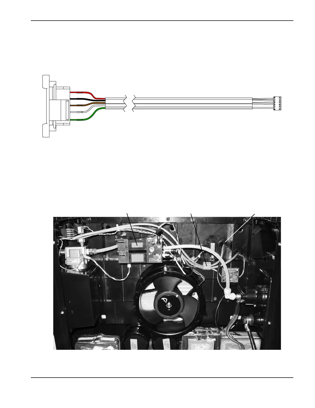
Figure 54
7. Route the RS-485 cable next to the 2 existing gray cables, above the solenoid valve and through the cable clip
attached to the center panel.
8. Push the small connector from the RS-485 cable through the center grommet in the center panel.
Figure 55
Red wire
Cable clip
Solenoid valve
Center grommet

Table of Contents

Other manuals for Hypertherm Powermax 125

Questions and Answers:

Question and Answer IconNeed help?

Do you have a question about the Hypertherm Powermax 125 and is the answer not in the manual?

Hypertherm Powermax 125 Specifications

General IconGeneral
BrandHypertherm
ModelPowermax 125
CategoryWelding System
LanguageEnglish

Related product manuals