198 Powermax125 Service Manual 808070
9 – Power Supply Component Replacement
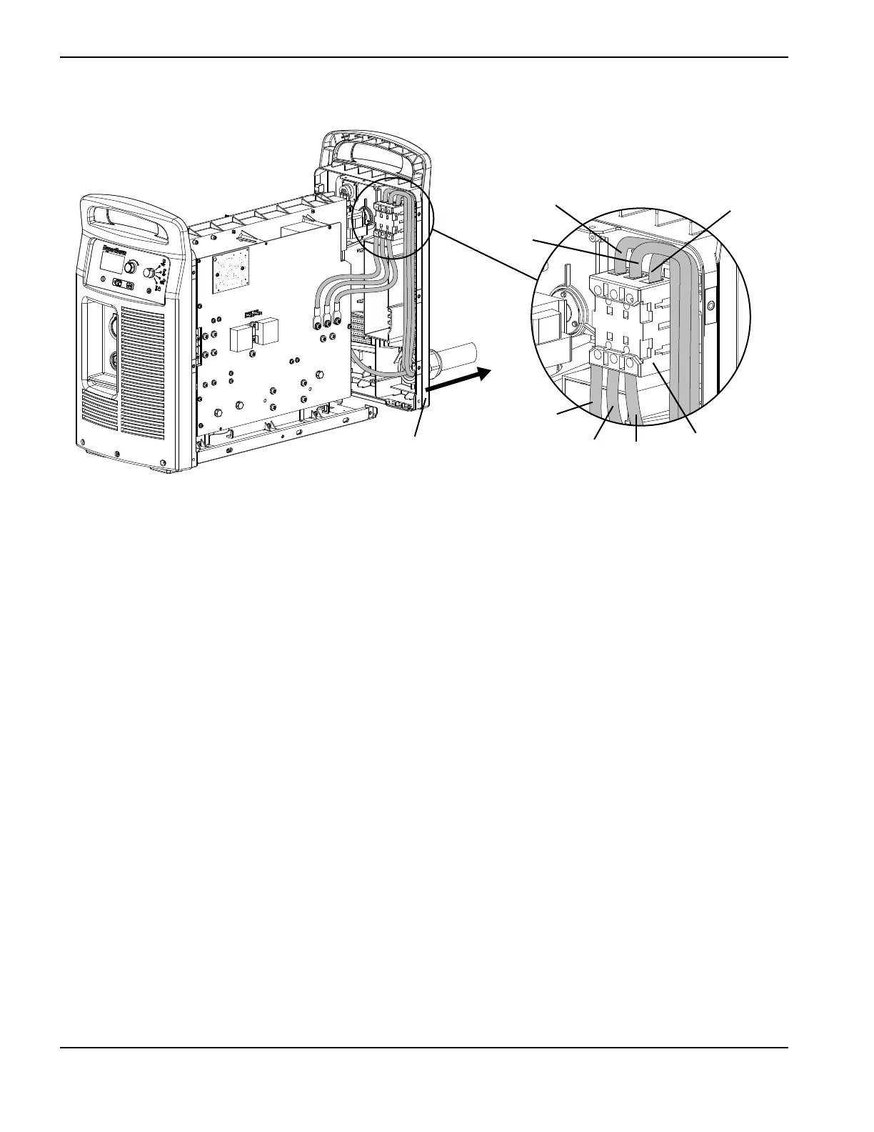
Figure 67
10. Remove the handle screw that secures the power switch handle to the post. (See Figure 68 on page 199.)
11. Pull the power switch handle straight off the post and set aside the handle and screw. If the white plastic cap does
not come off with the handle, pull the cap off the post as well.
12. Pry up the edge of the power switch label using a knife or blade screwdriver. If the optional RS-485 connector is not
installed, the label extends to the right side of the inlet gas fitting.
13. Peel off the entire label to expose the 4 mounting screws that secure the power switch to the rear panel.
14. Disengage the power switch from the rear panel by removing the 4 mounting screws.
L1
L2
L3
T1
T2
T3
Power switch
Rear panel