EasyManuals Logo

Hypertherm Powermax 125 Service Manual

Hypertherm Powermax 125
317 pages
To Next Page IconTo Next Page
To Previous Page IconTo Previous Page
Page #199 background imageLoading...
Page #199 background image
Powermax125 Service Manual 808070 199
9 Power Supply Component Replacement
Install the power switch
1. Secure the power switch to the rear panel by tightening the 4 supplied mounting screws to 17.3 kg-cm
(15 inch-pounds).
2. If the RS-485 connector is installed, bend and tear the new label at the perforation.
3. Peel the backing off the label and affix to the rear panel, being careful to align the hole in the label with the
corresponding hole in the rear panel.
4. Push the power switch handle straight onto the post and tighten the handle screw to 11.5 kg-cm (10 inch-pounds).
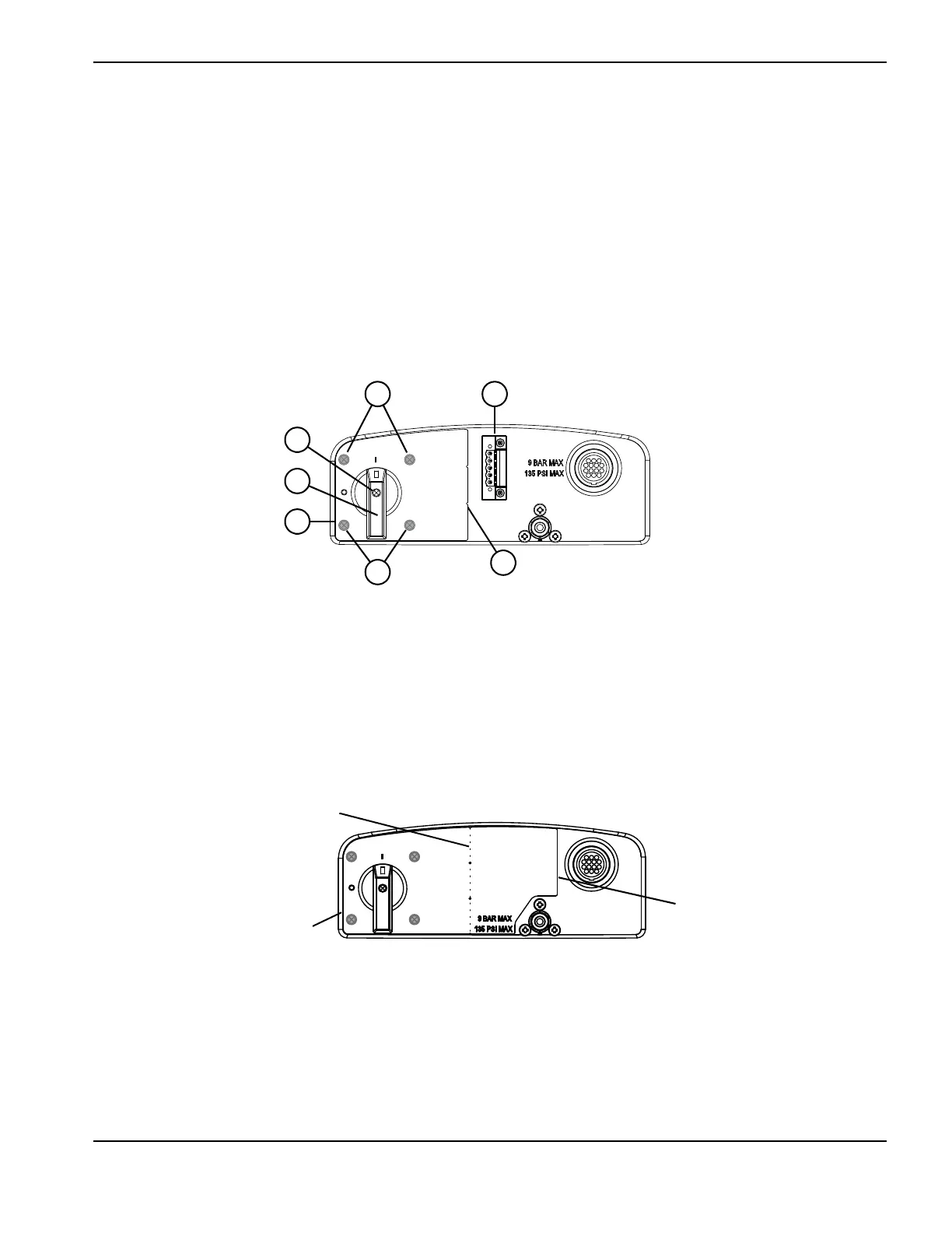
Figure 68 – Left half of label used when RS-485 connector is installed
Figure 69 – Full label used when RS-485 connector is not installed
1
2
3
4
4
5
6
1 Handle screw
2 Power switch handle
3 Left edge of label
4 Power switch screws (behind label)
5 Right edge of label ends at perforation
6 Optional RS-485 connector
Label perforation
Left edge of label
Right edge of label

Table of Contents

Other manuals for Hypertherm Powermax 125

Questions and Answers:

Question and Answer IconNeed help?

Do you have a question about the Hypertherm Powermax 125 and is the answer not in the manual?

Hypertherm Powermax 125 Specifications

General IconGeneral
Output Current30-125 A
Input Power15.2 kW
Open Circuit Voltage300 VDC
Gas SupplyClean, dry, oil-free air or nitrogen
Input Power Cable Length10 ft (3 m)
Rated Output Current125 A
Gas TypeAir or nitrogen
Cutting Capacity1-1/4 inch (32 mm)
Pierce Capacity1 inch (25 mm)
Input Voltage200-600 V, 3-PH
Duty Cycle100% @ 125 A
CertificationsCSA
Maximum Clean Cut Thickness1-1/4 inch (32 mm)
Cooling MethodFan-cooled
Torch OptionsHand

Related product manuals