200 Powermax125 Service Manual 808070
9 – Power Supply Component Replacement
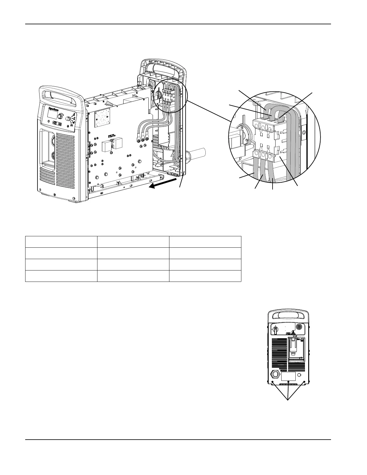
Figure 70
Table 14 – Power cord connections
5. Insert the red and black wires in the top of the auxiliary switch and
tighten the set screws to 11.5 kg-cm (10 inch-pounds). The red wire
connects to the “13” terminal, and the black wire connects to the
“14” terminal.
6. Insert the 3 power wires in the bottom of the power switch as shown in
Figure 70 and Table 14. Tighten the T1-T2-T3 set screws to 23 kg-cm
(20 inch-pounds).
7. Insert the 3 power wires in the top of the power switch as shown in
Figure 70 and Table 14. Tighten the L1-L2-L3 set screws to 23 kg-cm
(20 inch-pounds).
8. Lift up the end of the power supply base, and carefully slide the rear
panel against the base until the base sits securely on the panel. Tighten
the 3 mounting screws in the bottom of the rear panel to 23 kg-cm
(20 inch-pounds).
Wire CSA CE
L1 Black Brown
L2 White Black
L3 Red Gray
* Wire colors may vary in power cords not purchased from Hypertherm.
L1
L2
L3
T1
T2
T3
Power switch
Rear panel
Rear panel mounting screws