Powermax125 Service Manual 808070 207
9 – Power Supply Component Replacement
9. Install and tighten the remaining screws to 23 kg-cm (20 inch-pounds). Attach the previously removed wires to the
power board.
10. Attach any remaining connectors and reinstall the DSP board as explained in Install the DSP board on page 203.
11. Complete the following procedures:
a. See Install the component barrier on page 173.
b. See Install the power supply cover on page 172.
c. Reconnect the power and gas supply.
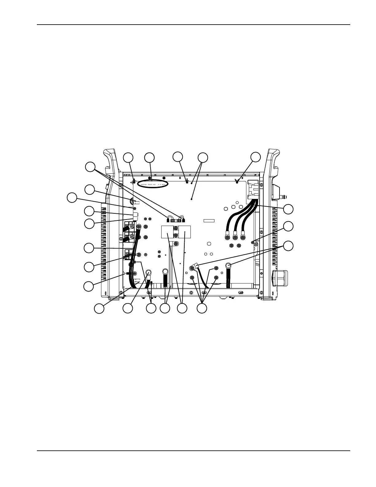
Figure 74 – 480 V / 600 V CSA power board
J6 J5
J3 J2 J1
J22 J21 J20 J19
J27
WORK
LEAD
J26
J25
+
_
+
_
RED
J18
ORG
J17
RED
J32
J11
B
R
J28
C152 C151
TP7
TP9
TP8
W
R
B
1
2
4
5
6
7
8
9
12
14
16
1110
15
1517
3
3
3
13
3
3
3
1 Gate drive connectors
2 J11
3 Board mounting screws (7)
4 J17
5 J18
6 Output inductor wires
7 Nozzle wires
8 Electrode wire
9 J32
10 Work lead
11 Transformer wires
12 4 μF capacitors
13 Capacitor screws (4)
14 PFC inductor wires
15 AC input wires (3)
16 Transformer mounting screws
17 J6, J5, J3, J2, and J1