Powermax125 Service Manual 808070 235
9 – Power Supply Component Replacement
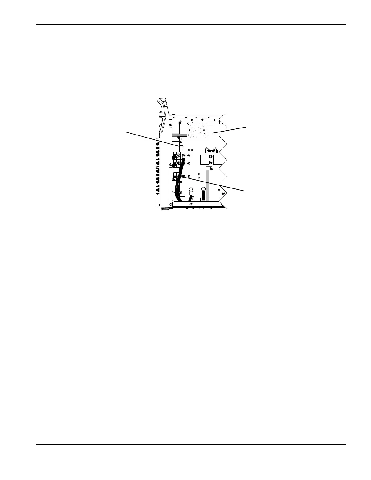
8. Secure the nozzle wires ring terminal to the power board by tightening the screw to 23 kg-cm (20 inch-pounds).
9. Plug the torch interface cable connector into the J17 socket on the power board. Align the orange wire in the
connector with the “ORG” that is printed on the power board.
Figure 92
10. Complete the following procedures:
a. See Install the fan shroud on page 216.
b. See Install the end panel bracket on page 175.
c. See Install the component barrier on page 173.
d. See Install the power supply cover on page 172.
e. Reconnect the power and gas supply.
J22
J27
WORK
LEAD
J26
_
RED
J18
ORG
J17
J32
J11
B
R
J28
RED
J17
Nozzle wire screw
Power board