EasyManuals Logo

Hypertherm Powermax 125 Service Manual

Hypertherm Powermax 125
317 pages
To Next Page IconTo Next Page
To Previous Page IconTo Previous Page
Page #245 background imageLoading...
Page #245 background image
Powermax125 Service Manual 808070 245
9 Power Supply Component Replacement
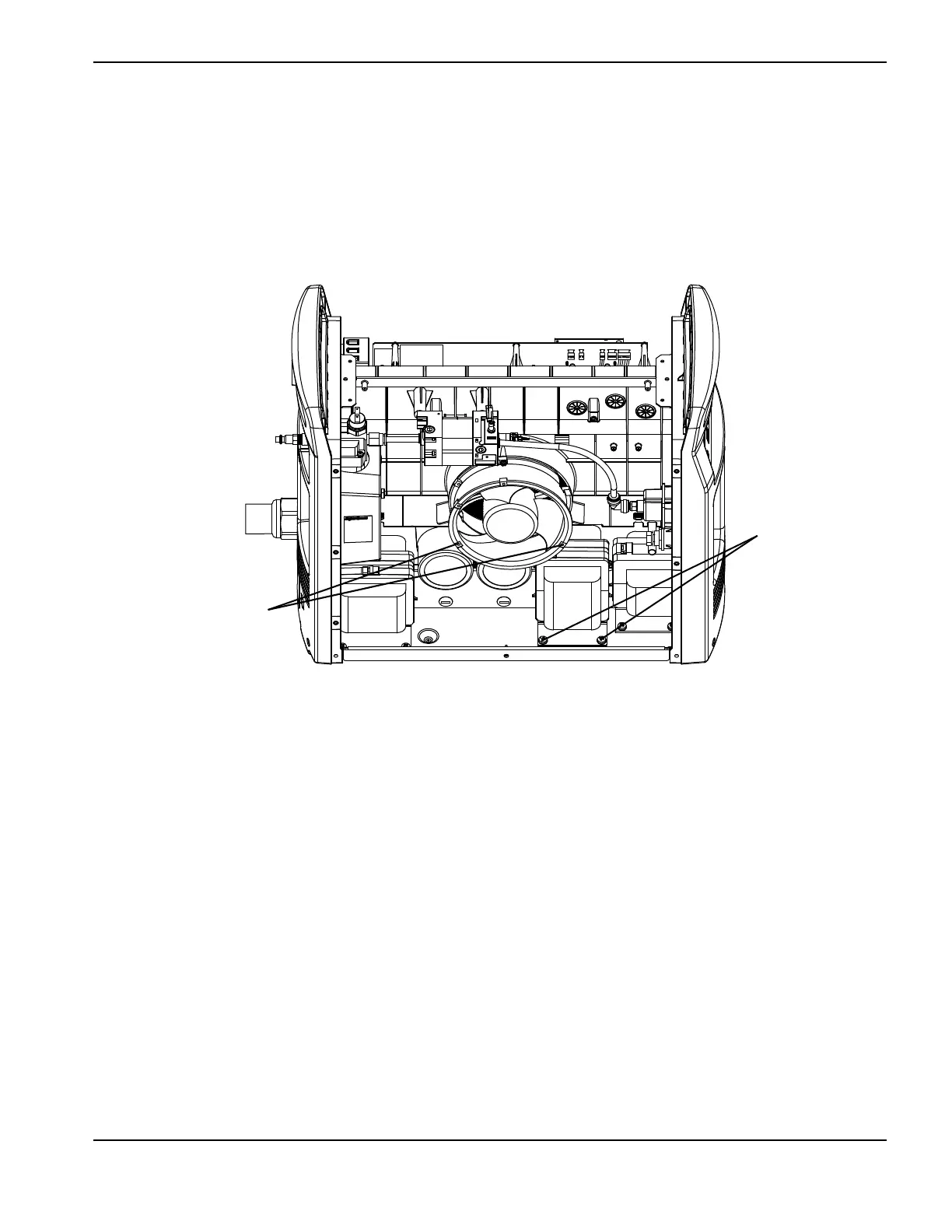
4. From the fan side, remove the 2 mounting screws from the base of the transformer.
5. Remove the bottom 2 fan mounting screws. The screws are located directly behind the bottom holes in the fan
housing flange.
6. Push the bottom of the fan to the left so that it will not interfere with the removal of the transformer.
Figure 100
J1 J2 J3 J5 J6
Bottom holes in fan housing
flange
Transformer
mounting screws

Table of Contents

Other manuals for Hypertherm Powermax 125

Questions and Answers:

Question and Answer IconNeed help?

Do you have a question about the Hypertherm Powermax 125 and is the answer not in the manual?

Hypertherm Powermax 125 Specifications

General IconGeneral
Output Current30-125 A
Input Power15.2 kW
Open Circuit Voltage300 VDC
Gas SupplyClean, dry, oil-free air or nitrogen
Input Power Cable Length10 ft (3 m)
Rated Output Current125 A
Gas TypeAir or nitrogen
Cutting Capacity1-1/4 inch (32 mm)
Pierce Capacity1 inch (25 mm)
Input Voltage200-600 V, 3-PH
Duty Cycle100% @ 125 A
CertificationsCSA
Maximum Clean Cut Thickness1-1/4 inch (32 mm)
Cooling MethodFan-cooled
Torch OptionsHand

Related product manuals