EasyManuals Logo

Hypertherm Powermax 125 Service Manual

Hypertherm Powermax 125
317 pages
To Next Page IconTo Next Page
To Previous Page IconTo Previous Page
Page #283 background imageLoading...
Page #283 background image
Powermax125 Service Manual 808070 283
10 Torch Component Replacement
6. Thread the torch body into the torch lead until snug.
The white wires of the lead should be facing up.
7. Use a 3/8-inch and 1/2-inch wrench together (or 2 adjustable wrenches) to tighten the gas fitting that secures the
torch body to the torch lead to 69.1 kg-cm (60 inch-pounds).
8. Tighten the pilot terminal screw to 17.3 kg-cm (15 inch-pounds).
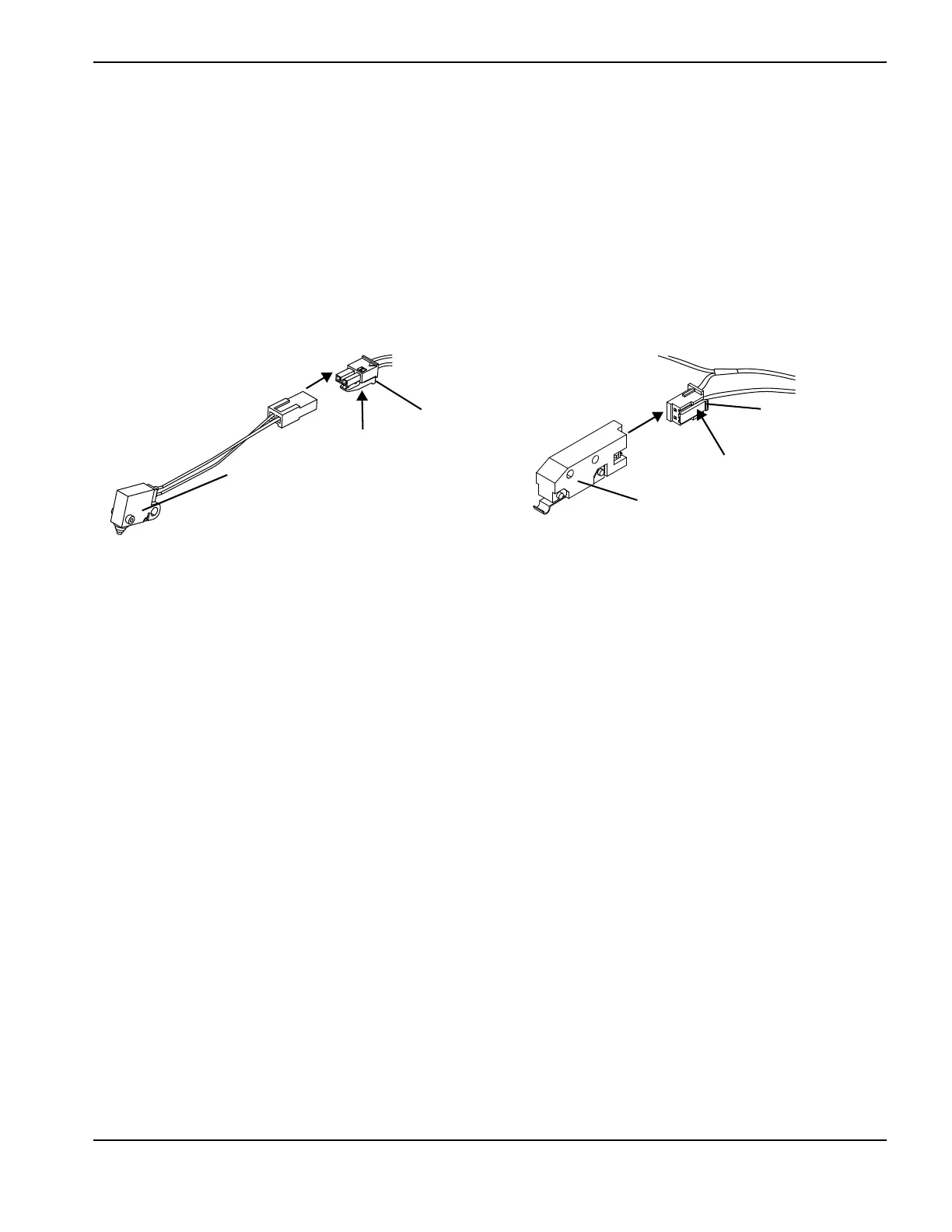
9. Connect the cap-sensor switch and start switch.
Figure 141
10. Complete the following procedures:
a. Install all of the components that you removed. See Install the handle on page 272.
b. Reconnect the torch and gas supply, and turn ON (I) the power.
Cap-sensor switch
Tab
Tab
Start switch

Table of Contents

Other manuals for Hypertherm Powermax 125

Questions and Answers:

Question and Answer IconNeed help?

Do you have a question about the Hypertherm Powermax 125 and is the answer not in the manual?

Hypertherm Powermax 125 Specifications

General IconGeneral
Output Current30-125 A
Input Power15.2 kW
Open Circuit Voltage300 VDC
Gas SupplyClean, dry, oil-free air or nitrogen
Input Power Cable Length10 ft (3 m)
Rated Output Current125 A
Gas TypeAir or nitrogen
Cutting Capacity1-1/4 inch (32 mm)
Pierce Capacity1 inch (25 mm)
Input Voltage200-600 V, 3-PH
Duty Cycle100% @ 125 A
CertificationsCSA
Maximum Clean Cut Thickness1-1/4 inch (32 mm)
Cooling MethodFan-cooled
Torch OptionsHand

Related product manuals