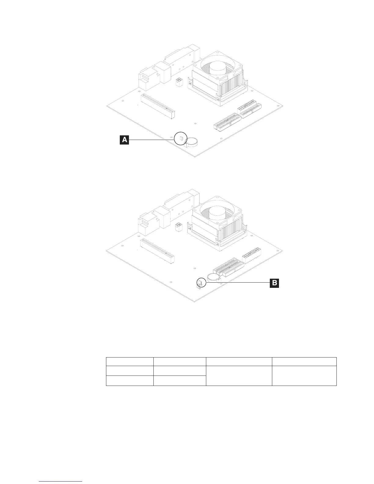
3. See A in Figure 102 or B in Figure 103 to locate your CMOS jumper on the
planar. See Table 7 for the correct pins and position to clear your CMOS
settings.
Table 7. CMOS jumper and pin location by model
Model CMOS Jumper Pins for normal operation Pins to clear CMOS
721 JP5
1-2 2-3
741, 781 JP4
4. Move the pins to position 2-3 and wait for 5 seconds.
5. Return the pins to position 1-2.
6. Re-plug the AC cord and power-on the system. Your system now has the
default CMOS settings.
Note:
Restoring the CMOS default settings may be necessary if a password is lost
or forgotten.
Figure 102. Location of CMOS jumper—Model 741 and 781
Figure 103. Location of CMOS jumper—Model 721
Updated October 31, 2007
Chapter 5. Diagnostics and configuration settings 101
 Loading...