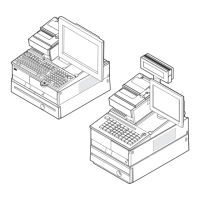
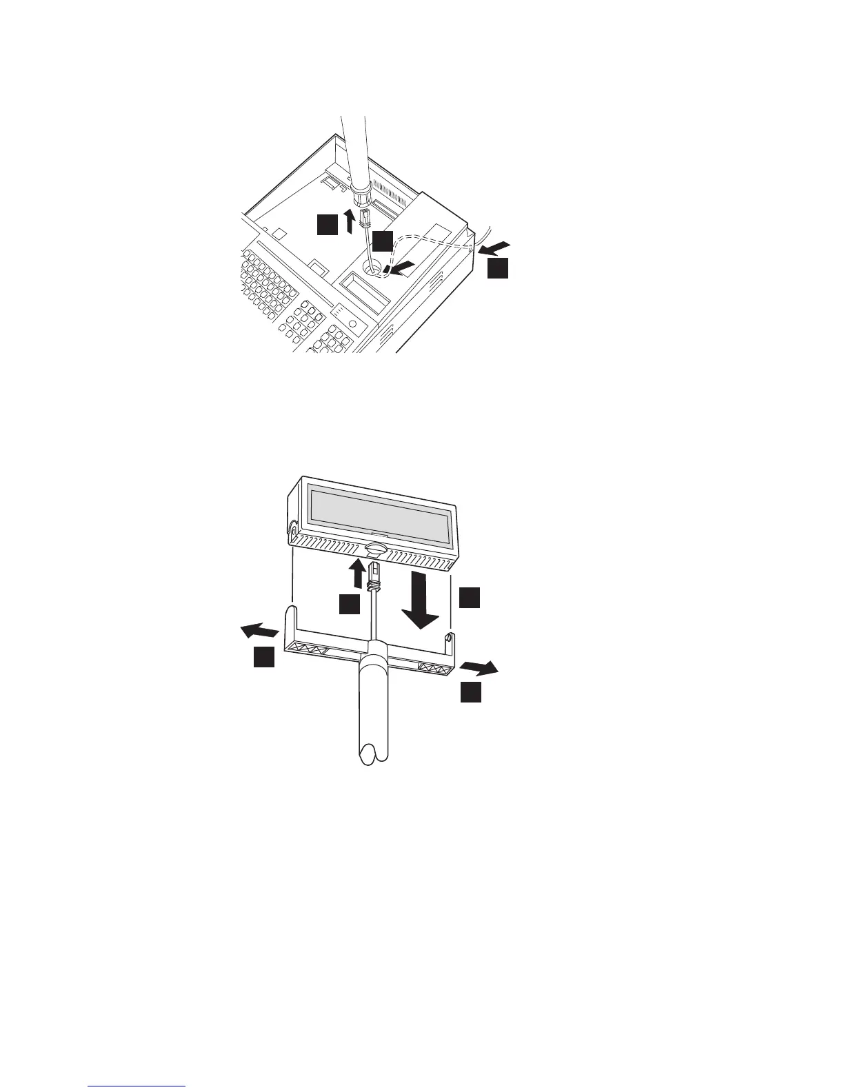
3. Route the character/graphics display cable from the rear of the POS terminal
A, through the hole on the filler B, and through post C as shown in
Figure 64.
4. Connect the display cable A to the display unit. See Figure 65.
5. Spread the arms on the character/graphics display B slightly, and install the
display unit C, as shown in Figure 65.
2
B
A
C
Figure 64. Routing the character/graphics display cable
B
B
A
C
Figure 65. Installing the character/graphics display
Updated October 31, 2007
Chapter 4. Installing external options 69