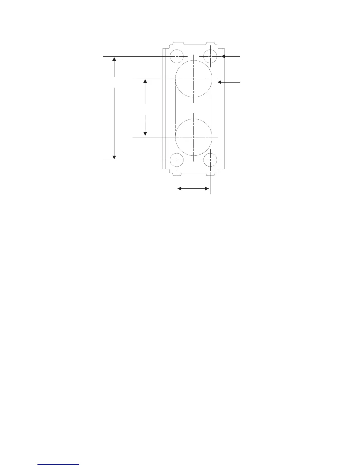
Note: To route cables through the counter, drill two 7/8-in. holes through the
counter. Trim the remaining material between the holes with a small saw
or chisel.
2. Place the pedestal so that the receiving bolts align with the screw holes in the
counter.
3. Use the enclosed M6 screws to secure the pedestal to the counter as shown in
Figure 76 on page 78. The slots located in the metal support bracket allow you
to position the pedestal for maximum stability.
4. Route the video and power cables down through the pedestal.
5. Attach the cable to the appropriate ports in the system unit.
35 mm
(1.37 in.)
20 mm
(0.80 in.)
62 mm
(2.44 in.)
8 mm (0.31 in.)
diameter
22 mm (0.87 in.)
diameter
Figure 77. Pedestal mounting template
Updated October 31, 2007
Chapter 4. Installing external options 79
 Loading...