Chapter 6 Illustrated Parts Breakdown
411
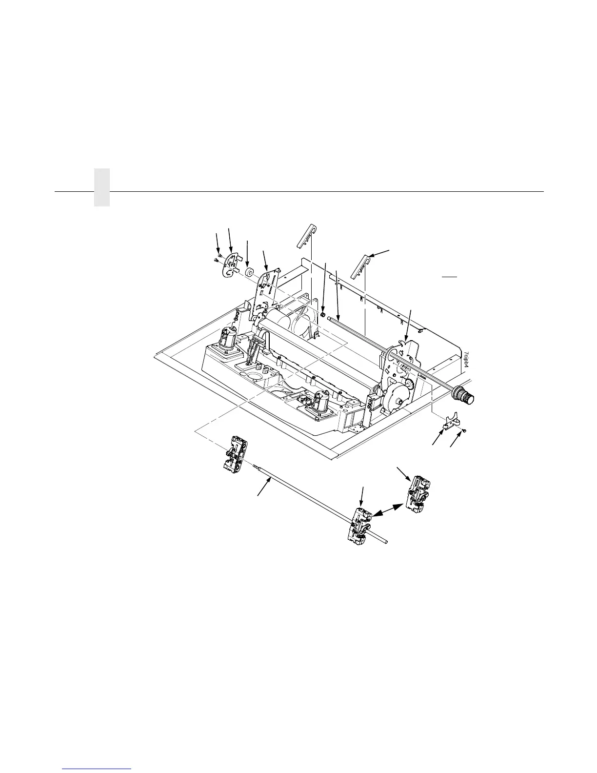
Figure 44. This illustrated parts breakdown shows the tractors and tractor shafts.
1
2
3
4
5
6
11
12
8
7
9
10a
IMPORTANT: The barrier panel is
removed in this illustration to more
clearly illustrate the mounting
hardware of the tractor shafts. In
order to preserve correct alignment of
the side plates, however, the barrier
panel must remain installed and
fastened if the splined or support
shafts are removed or replaced. The
barrier panel is shown in Figure 39
and Figure 40.
10b

 Loading...


