54 IBM Flex System V7000 Storage Node Introduction and Implementation Guide
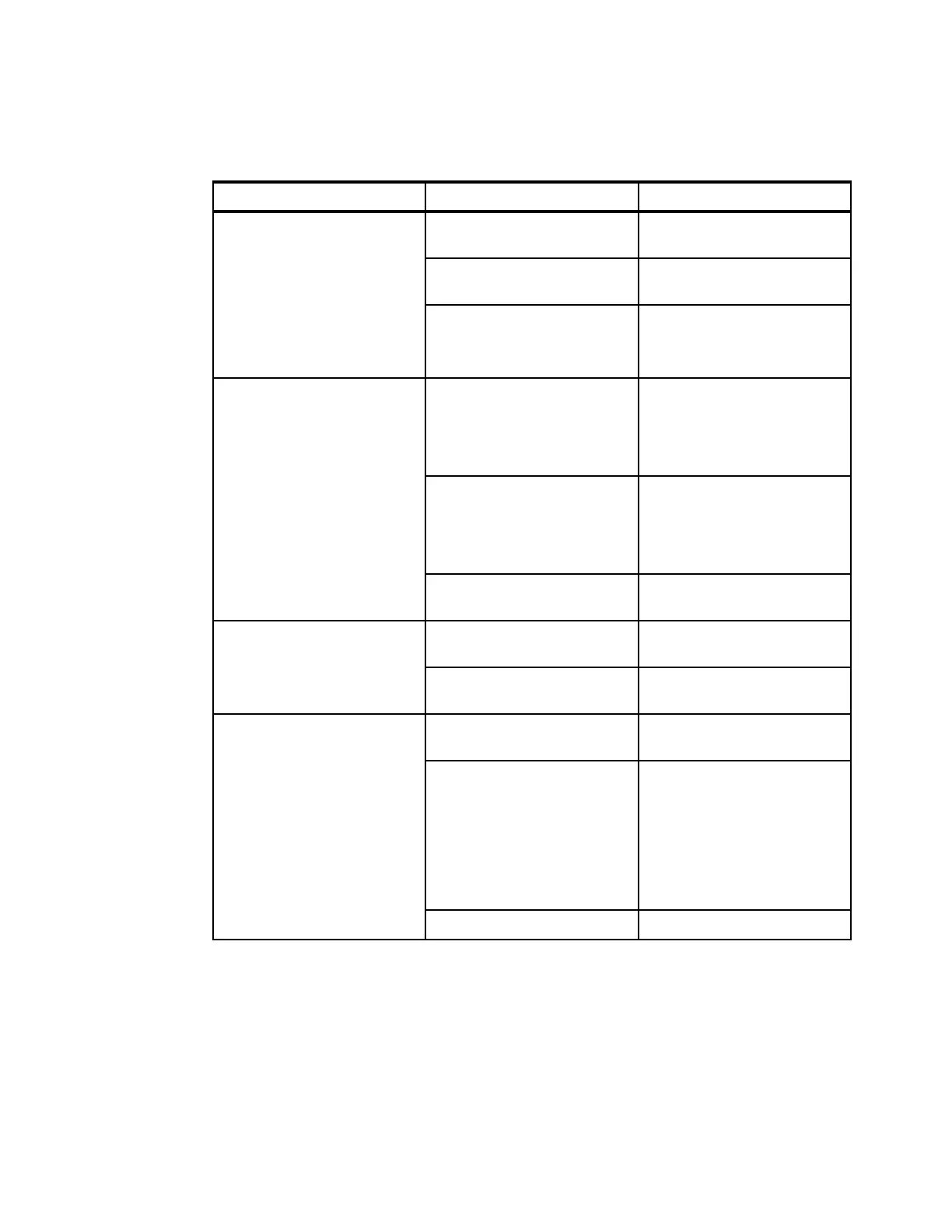
In Table 2-5, the LED indicators are defined for the control enclosure; some of them are also
used on the expansion enclosure as well.
Table 2-5 Control enclosure LED description
LED group LED name Meaning
Enclosure Indicator
The Enclosure Indicator LEDs
on the righthand control
canister are used as the
primary enclosure LEDs.
The left hand control canister
LEDs are used when the
righthand is not available.
Check Log Software fault telling you to
check the errorlog for details.
Identify Used for identifying the
selected enclosure.
Fault Indicates that a hardware fault
has occurred.
Controller Indicators Power Slow Blink - Power
available but Processor
shutdown.
Fast blink - doing POST.
On solid - Powered up.
Status Off - not operational.
Solid - in a cluster.
Slow blinking - in cluster or
service state.
Fast blink - is upgrading.
Activity Activity LED blinks to show that
there is I/O activity.
Controller FRU
Control canister hardware fault
Control Hardware problem with the
control canister.
Internal FRU Problem with an internal FRU
such as the network adapters.
Battery Indicators In Use Fast blink - System is shutting
down on battery power.
Status Slow blink - Charging, but
has enough power to boot
the canister.
Fast blink - Charging, and
does not have enough.
power to boot the canister
(Error 656).
On solid - Fully charged.
Fault On - Hardware fault detected.