3 Analog I/O Modules
30-24 WindO/I-NV4 User’s Manual
3.3 Device Allocation
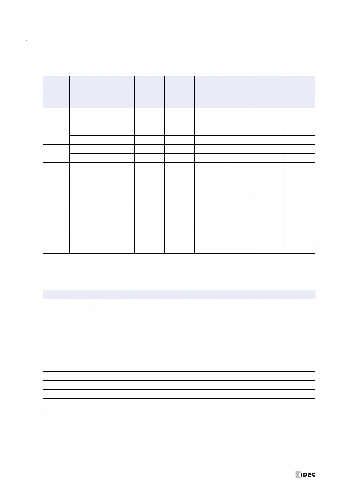
● Analog Input Module
Allocation of device address for the analog input module is shown below.
For details about the parameter setting values, refer to “ Analog Input Parameter Setting Values” on page 30-24.
Analog Input Parameter Setting Values
The parameter setting values are as follows.
■ Signal type
Channel
Parameter R/W
FC6A-
J2C1
FC6A-
J4A1
FC6A-
J8A1
FC6A-
J4CN1
FC6A-
J4CH1Y
FC6A-
J8CU1
No.
Address
Number
Address
Number
Address
Number
Address
Number
Address
Number
Address
Number
CH0
Analog input data R +0 +0 +0 +0 +0 +0
Analog input status R +1 +1 +1 +1 +1 +1
CH1
Analog input data R +2 +2 +2 +2 +2 +2
Analog input status R +3 +3 +3 +3 +3 +3
CH2
Analog input data R ― +4 +4 +4 +4 +4
Analog input status R ― +5 +5 +5 +5 +5
CH3
Analog input data R ― +6 +6 +6 +6 +6
Analog input status R ― +7 +7 +7 +7 +7
CH4
Analog input data R ――+8 ――+8
Analog input status R ――+9 ――+9
CH5
Analog input data R ――+10 ――+10
Analog input status R ――+11 ――+11
CH6
Analog input data R ――+12 ――+12
Analog input status R ――+13 ――+13
CH7
Analog input data R ――+14 ――+14
Analog input status R ――+15 ――+15
Setting Value Signal Type
0 Unused
1 0 to 10 V
2 -10 to +10 V
3 0 to 20 mA
4 4 to 20 mA
5 Type K thermocouple
6 Type J thermocouple
7 Type R thermocouple
8 Type S thermocouple
9 Type B thermocouple
10 Type E thermocouple
11 Type T thermocouple
12 Type N thermocouple
13 Type C thermocouple
14 Pt100
15 Pt1000
16 Ni100
 Loading...