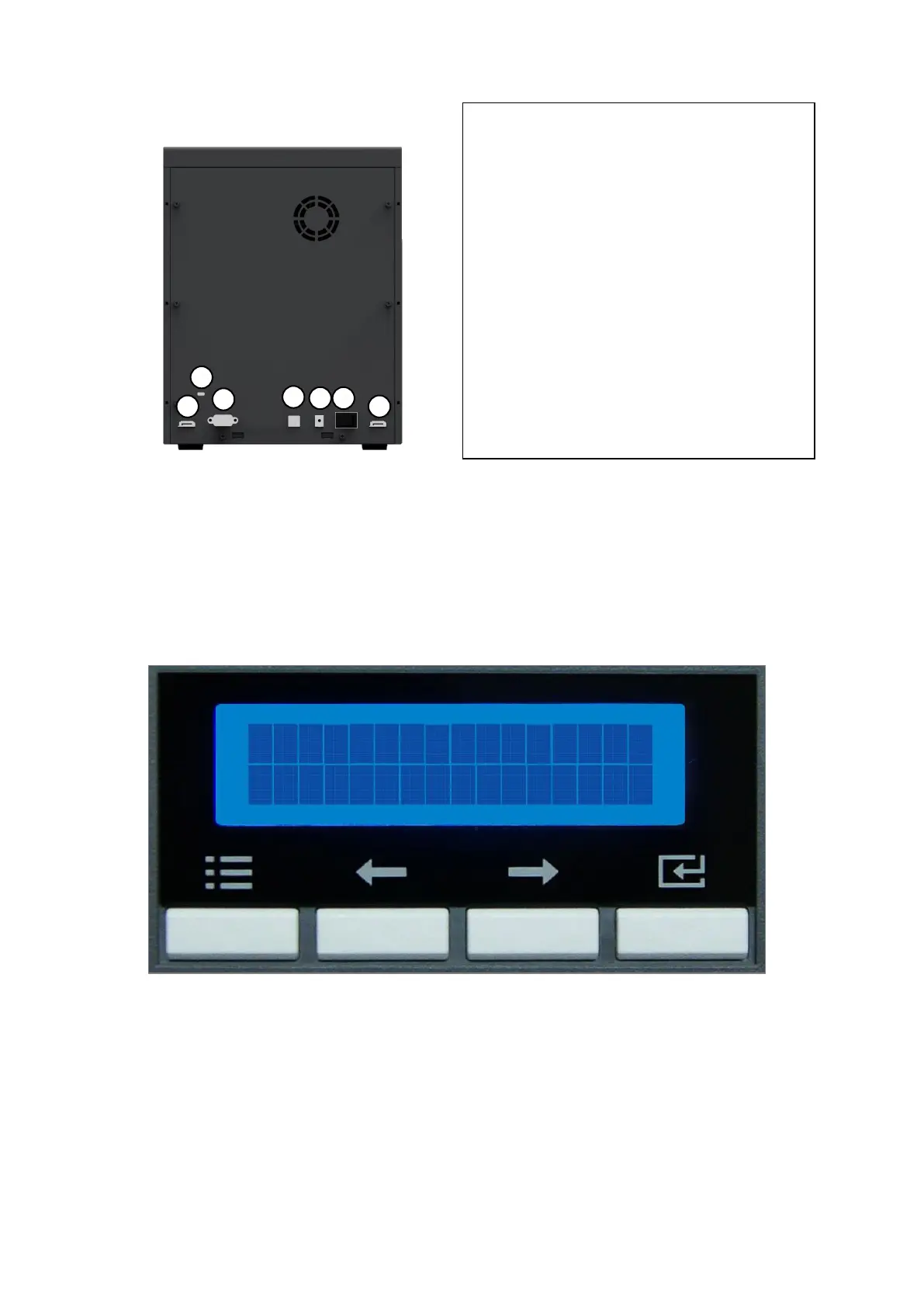
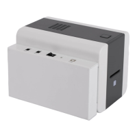
EasyManua.ls Logo

idp SMART-70 - Figure 10 Rear Side of Laminator; Figure 11 Control Panel of Laminator

idp SMART-70
106 pages
Print Icon
To Next Page IconTo Next Page
To Previous Page IconTo Previous Page
Loading...
23
Figure 10 Rear side of Laminator
Control panel of Laminator consists of 2 lines LCD and 4 buttons. The 4 buttons have the
functions as shown in the figure 11
Figure 11 Control panel of Laminator
0
1
0
2
0
3
0
2
0
4
0
5
0
6
Kensington lock
Kensington lock is usable
Communication port
To communicate between SMART-70 modules,
please connect to an adjacent module.
Serial communication port
This port is to communicate with external
device except SMART-70 modules.
USB device port
When Laminator is used without the Printer,
this port is to communicate with PC.
Power port
Please connect the 24V DC power adaptor
provided with Laminator.
Power switch
Turn On/Off
Menu/Cancel
Left/Up
Right/Down
Select/OK

Table of Contents

Related product manuals