SECTION 6—WHEEL LOCKS
ProSPIN™ X4™ 38 Part No 1125104
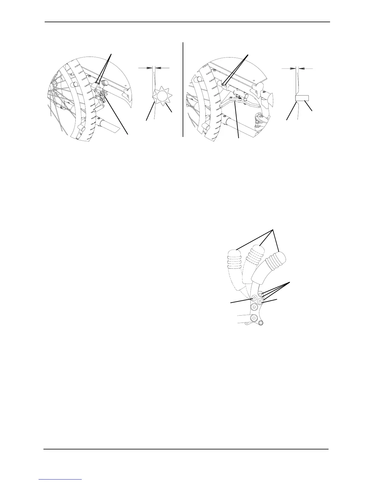
FIGURE 6.1 Replacing/Adjusting the Wheel Locks
Changing Wheel Lock Handle Position
NOTE:Forthisprocedure,refertoFIGURE6.2.
1. Loosen,butDONOTremove,therearhandlemountingscrew.
2. Removethefronthandlemounting
screwandlocknut.
3. Alignthefronthandlemountinghole
withoneofthreedesiredmounting
positionsonthewheellock.
4. Usingthefronthandlemountingscrew
andlocknut,securethehandletothe
wheellock.
5. Securelytightenthefrontandrear
handlemountingscrewsandlocknuts.
6. RepeatSTEPS1‐5onremainingwheel
lockhandle.
FIGURE 6.2 Changing Wheel Lock Handle
Position
Converting Wheel Lock From Push-to-Lock to
Pull-to-Lock or Pull-to-Lock to Push-to-Lock
NOTE:Forthisprocedure,refertoFIGURE6.3onpage39.
Converting From Push-to-Lock to Pull-to-Lock
1. Removesetscrewfromthelowerstopposition(Detail“A”).
3/16 inch
(1/8-inch)
Tire
Wheel
Lock
Shoe
Mounting Screws
Wheel Lock
Wheel Lock
Under Mount Wheel Lock
Push-to-Lock or Pull-to-Lock Wheel Locks
3/16 inch
(1/8-inch)
Wheel
Lock
Shoe
Tire
Mounting Screws
Wheel lock Handle
Front Handle
Mounting
Screw and
Locknut
Rear Handle
Mounting
Screw
Mounting
Positions