SECTION 11—WHEELS
ProSPIN™ X4™ 70 Part No 1125104
3. Makethefollowingadjustments:
•Ifthequad‐releasehandleisnotreleasingthelockingpinscompletely,rotatethe
quad‐releasehandleapproximatelyone‐quarterturnclockwise.
•Ifthequad‐releasehandlehitsthespokesoftherearwheelwhenassembled,rotate
thequad‐releasehandleapproximatelyone‐quarterturncounterclockwise.
4. Tightenthelockingscrew.
5. Reinstalltherearwheelandquad‐releaseaxleontotheaxlebushing.
WARNING
Make sure the detent pin and locking pins of the quad-release axle are fully released
BEFORE operating the wheelchair.
Keep locking pins clean.
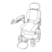
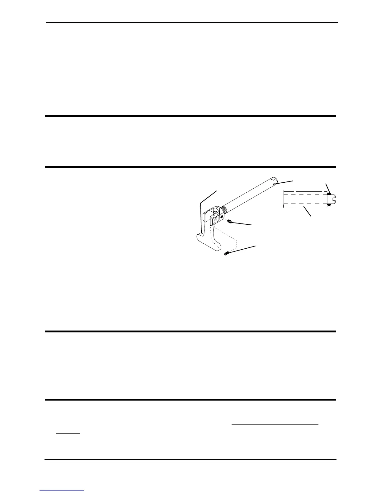
6. Flipthehandleofthequad‐releaseaxle
downtoreleasethedetentpinensuring
thatthelockingpinsarefullyreleased.
7. Repeattheaboveproceduresuntilthe
quad‐releaseaxlelockscorrectly.
Removing the Play From the Rear
Wheels
1. Withtherearwheelandquad‐release
axlestillmountedontothewheelchair,
tightenthelengthadjustingscrewuntil
thereisnoinandoutmovementofthe
quad‐releaseaxleandrearwheel.
FIGURE 11.4 Adjusting Quad-Release
Handles
Adjusting the Rear Wheel Camber
CAUTION
DO NOT overtighten mounting screws that secure the axle mounting plates to the
wheelchair frame. Damage to the wheelchair frame can occur.
The maximum degree of camber the wheelchair will allow is 6°, or three additional
camber spacers. Using more than three total camber spacers may cause damage to
the wheelchair.
NOTE:Forthisprocedure,refertoFIGURE11.5onpage71.
1. Removetherearwheelfromthewheelchair.RefertoRemoving/InstallingRear
Wheelsonpage 67.
2. Loosen,butDONOTremovethetwotopmountingscrewsthatsecuretheaxle
mountingplatetothewheelchair.
Length Adjustment Screw
Locking Screw
Quad-Release
Handle
Axle
Bushing
Locking Pin