SECTION 11—WHEELS
Part No 1125104 71 ProSPIN™ X4™
3. Removethebottommountingscrew,locknut,twowashers,camberspacer(s)(if
present)andlocknutsthatsecuretheaxlemountingplateandanti‐tipperbracket(if
present)tothewheelchairframe.
4. Installorremovethenumberofcamberspacerstoachievethedesiredcamberangle:
CAMBER ADJUSTMENT
NOTE:Sizeofthebottommountingscrewswillchangeaccordingtonumberofcamberspacers
presentandifanti‐tippersareused.
5. Installthetwobottommountingscrews,washers,camberspacer(s)andlocknuts,that
securetheaxlemountingplateandanti‐tipperbracket(ifpresent)tothewheelchair
frame.
6. Securelytightenthetwotopmountingscrewsandlocknutsthatsecuretheaxle
mountingplatetothewheelchairframe.
7. Reinstalltherearwheelontothewheelchair.RefertoRemoving/InstallingRear
Wheelsonpage 67.
8. RepeatSTEPS1‐7fortheoppositesideofthewheelchair.
NOTE:Makesurethenumberofcamberwashersisthesameforbothrearwheels.Thiswillhelp
avoidaʺ3‐wheelingʺsituation.
9. Rolltherearwheels.Ifrearwheelsrubthewheelchairatanypoint,adjustthe
wheelbase
width.RefertoAdjustingWheelbaseWidthonpage 74.
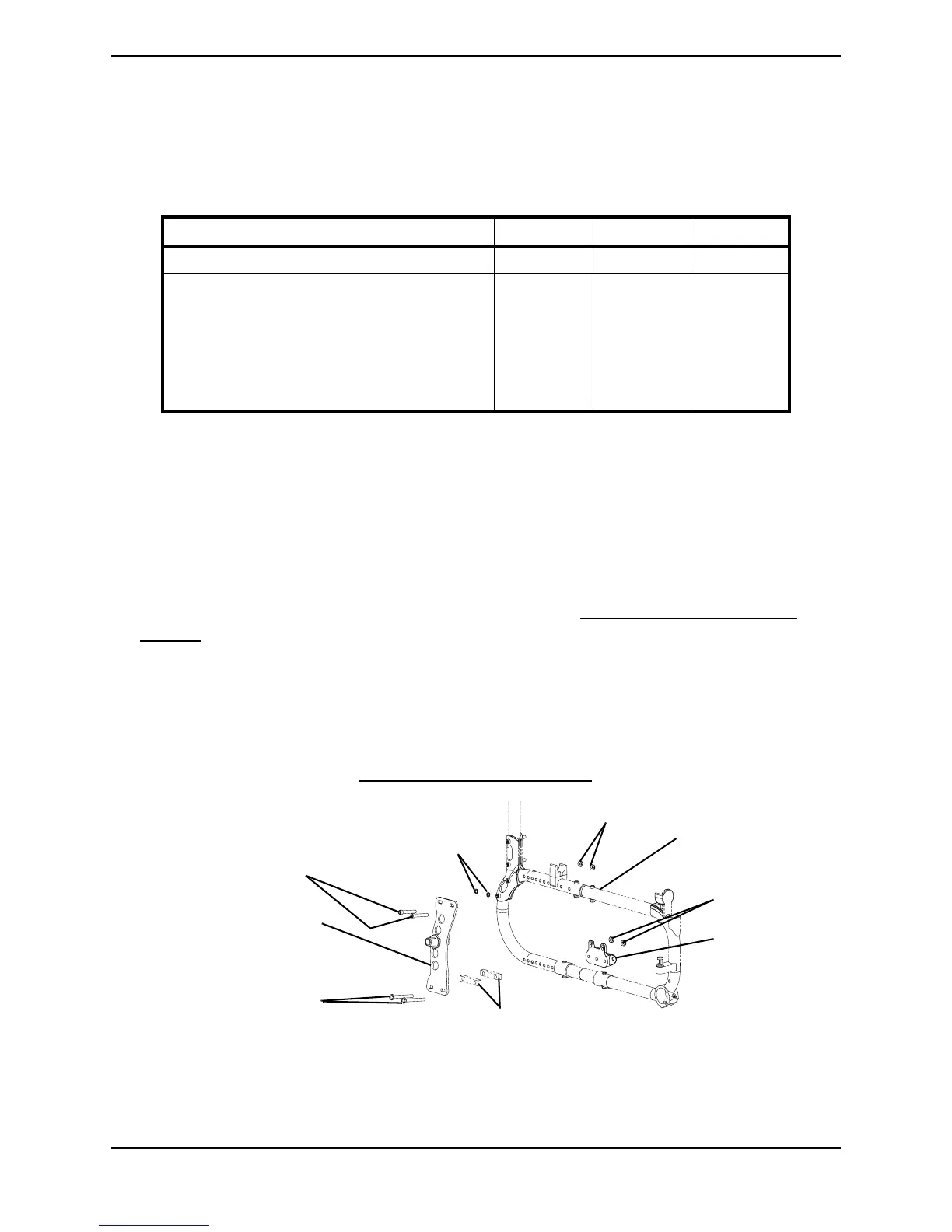
FIGURE 11.5 Adjusting the Rear Wheel Camber
CAMBER ANGLES 0° 3° 6°
NUMBER OF CAMBER SPACERS: 012
BOTTOM MOUNTING SCREW LENGTH
W/O ANTI-TIPPERS
Upper Mounting Screws:
Lower Mounting Screws:
W/ ANTI-TIPPERS
Upper Mounting Screws:
Lower Mounting Screws:
1½ inches
1½ inches
1½ inches
1¾ inches
1½ inches
2 inches
1¾ inches
2¼ inches
1¾ inches
2¼ inches
1¾ inches
2½ inches
Top Mounting Screws
Washers
Locknuts
Bottom Mounting Screws
Axle Plate
Camber Spacers (If Present)
Anti-Tipper
Bracket
Wheelchair Frame
Locknuts