P/N 960-000164R_Rev. 3 {EDP #213631} © 2018, JAPAN CASH MACHINE CO., LTD.
Section 4 iPRO-RC™ Series Banknote Recycler Disassembly/Reassembly
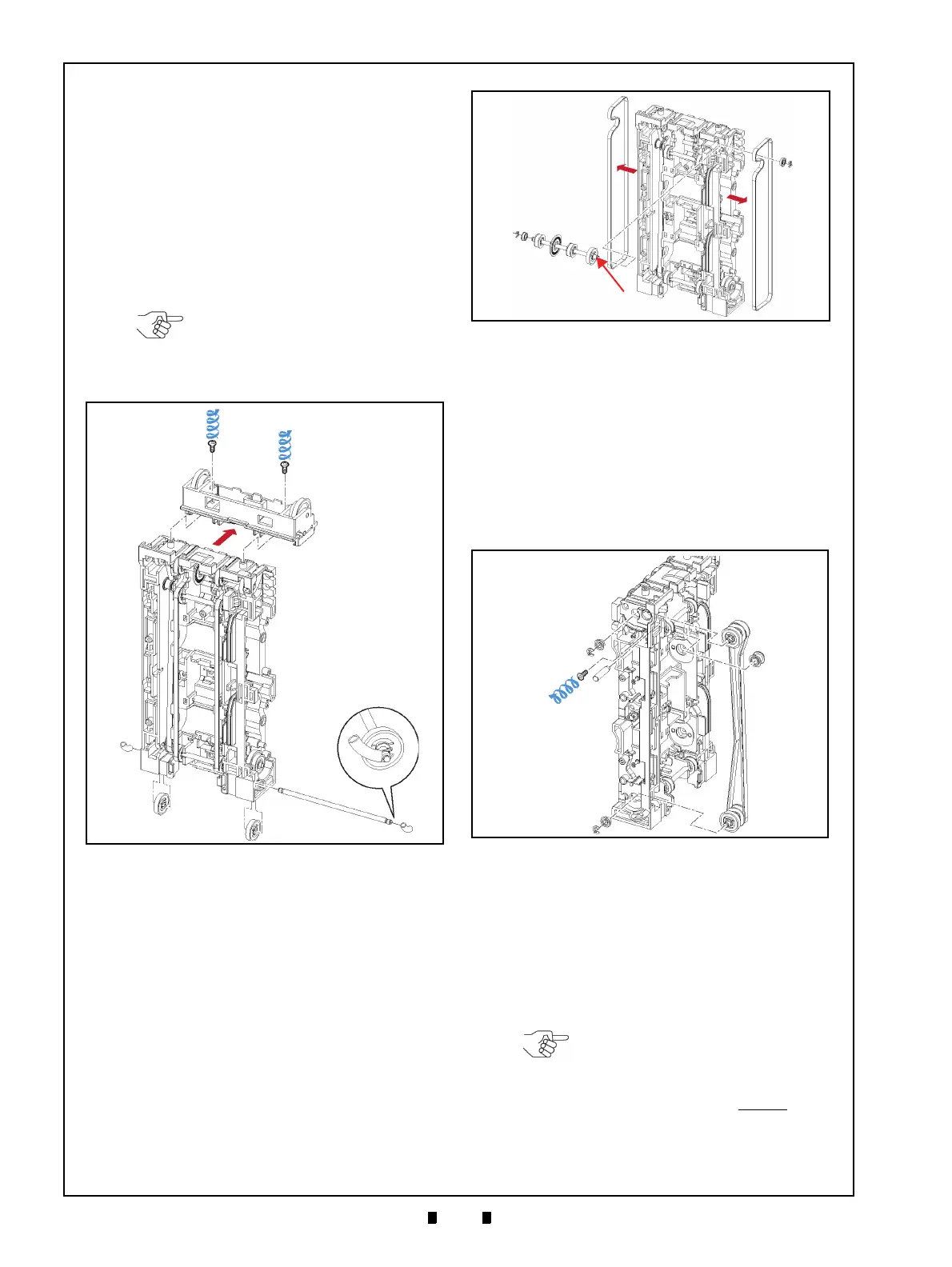
Timing Belt Removal
To remove the Timing Belt, proceed as follows:
1. Remove the two (2) Mounting Screws (Figure 4-
22 a
1
& a
2
) retaining the Rear Transport Upper
Frame (Figure 4-22 b) in
place, and take the Rear
Transport Upper Frame off of the Rear T
ransport
Assembly.
2. Remove the two (2) Springs (Figure 4-22 c
1
& c
2
)
retaining the single (1) Shaft (Figure 4-22 d)
in its
rest position, and remove the Shaft and the two
(2
) Gears (Figure 4-22 e
1
& e
2
).
3. Remove the two (2) E-Rings (Figure 4-23 a
1
&
a
2
), the two (2) Bearings (Figure 4-23 b
1
& b
2
),
the single (1) Shaft (Figure 4-23 c), the single (1)
Gear (Figure 4-23 d),
the single (1) Encoder (Fig-
ure 4-23 e) and th
e two (2) Pulleys (Figure 4-23 f
1
& f
2
) from the Transport Assembly.
4. Remove the two (2) Timing Belt Covers (Figure
4-23 g
1
& g
2
) from both the left and right sides of
the Rear Transport Assembly.
5. Remove the single (1) Shaft Mounting Screw
(Figure 4-24 a) and
pull the single (1) Shaft and
related Bearing out from
the Rear Transport
Assembly (Figure 4-24 b
1
& b
2
).
6. Remove the two (2) E-Rings (Figure 4-24 c
1
&
c
2
), and the two (2) related Bearings (Figure 4-24
d
1
& d
2
); then pull the two (2) Shafts (Figure 4-24
e
1
& e
2
) out and remove the single (1) Timing
Belt with its related pulleys (Figure 4-24 f) fr
om
the Assembly.
Pick Roller Removal
To remove the Pick Roller, proceed as follows:
1. Remove the two (2) Mounting Screws (Figure 4-
25 a
1
& a
2
) retaining the two (2) RC Centering
Guides (Figure 4-25 b
1
& b
2
) in place, and
remove the RC Centering Gui
de from the Cash
Box.
NOTE: When re-inserting the Shaft,
press the edge of the Shaft in using
the Springs visible from the front
side of the Rear Transport Assembly
(Figure 4-22 f).
Figure 4-22 Rear Transport Upper Frame &
Shaft Removal
Figure 4-22 Rear Transport Upper Frame
& Shaft Removal
Figure 4-23 Timing Belt Cover Removals
Figure 4-23 Timing Belt Cover Removals
Figure 4-24 Timing Belt/Pulley Removal
Figure 4-24 Timing Belt/Pulley Removal
NOTE: One of the two (2) RC
Centering Guides contains a Prism
installed in its Plate to detect the
Cash Box (Figure 4-25 c). Ensure
that this Guide Plate is always
re-
installed in the upper position of the
Cash Box.

 Loading...

