P/N 960-000164R_Rev. 3 {EDP #213631} © 2018, JAPAN CASH MACHINE CO., LTD.
Section 2 iPRO-RC™ Series Banknote Recycler Installation
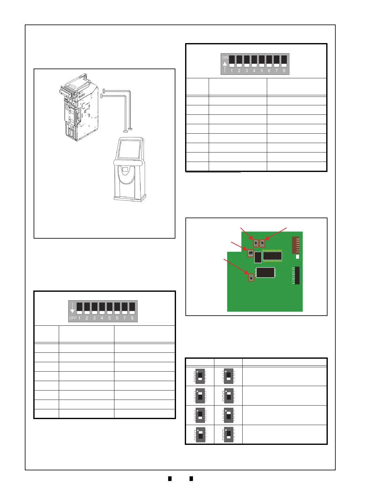
Cable Interconnection
Figure 2-3 illustrates the Cable interconnection
requirements between the iPRO-RC™ and a Host
Machine.
DIP Switch Configuration
This section provides the denomination DIP Switch
Block settings for the iPRO-RC
™ Unit.
Switch Configuration
The CPU Circuit Board contains four (4) DIP
Switches on the Circuit Board (Figure 2-4).
DIP Switches identify an RS232C, Photo-Coupler,
or ccTalk configuration selection (Table 2-3).
Table 2-1 iPRO Transport Unit DIP Switch Settings
iPRO Transport Unit DIP Switches
Switch
No.
Switch ON Switch OFF
1 VEND 1 INHIBIT VEND 1 ACCEPT
2 VEND 2 INHIBIT VEND 2 ACCEPT
3 VEND 3 INHIBIT VEND 3 ACCEPT
4 VEND 4 INHIBIT VEND 4 ACCEPT
5 VEND 5 INHIBIT VEND 5 ACCEPT
6 VEND 6 INHIBIT VEND 6 ACCEPT
7 VEND 7 INHIBIT VEND 7 ACCEPT
8OFF OFF
Figure 2-3 Cable Interconnection
Figure 2-3 Cable Interconnection
a
b
c
a) iPRO-RC™ Unit
b) Interface Connector
c) Interconnecting Harness
d) Host Machine (Game Machine, Kiosk, etc.)
e) Power Connection Harness
Table 2-2 iPRO-RC Unit DIP Switch Settings
*
iPRO-RC Unit DIP Switches
Switch
No.
Switch ON Switch OFF
1 Reserved Reserved
2 Reserved Reserved
3 Reserved Reserved
4 Reserved Reserved
5 Reserved Reserved
6 Reserved Reserved
7 Reserved Reserved
8 Reserved Reserved
*. Refer to each Country’s “Software Information Sheet” for making the
proper Switch settings.
Table 2-3 CPU Board Switch Configurations
Switch 5 Switch 3 Signal Name
RS232C
Photo-Coupler Isolation
cc-Talk
Reserved
Figure 2-4 CPU Board Switch Locations
Figure 2-4 CPU Board Switch Locations
Switch #3
Switch #5
Switch #4
Switch #2