P/N 960-000164R_Rev. 3 {EDP #213631} © 2018, JAPAN CASH MACHINE CO., LTD.
Section 4 iPRO-RC™ Series Banknote Recycler Disassembly/Reassembly
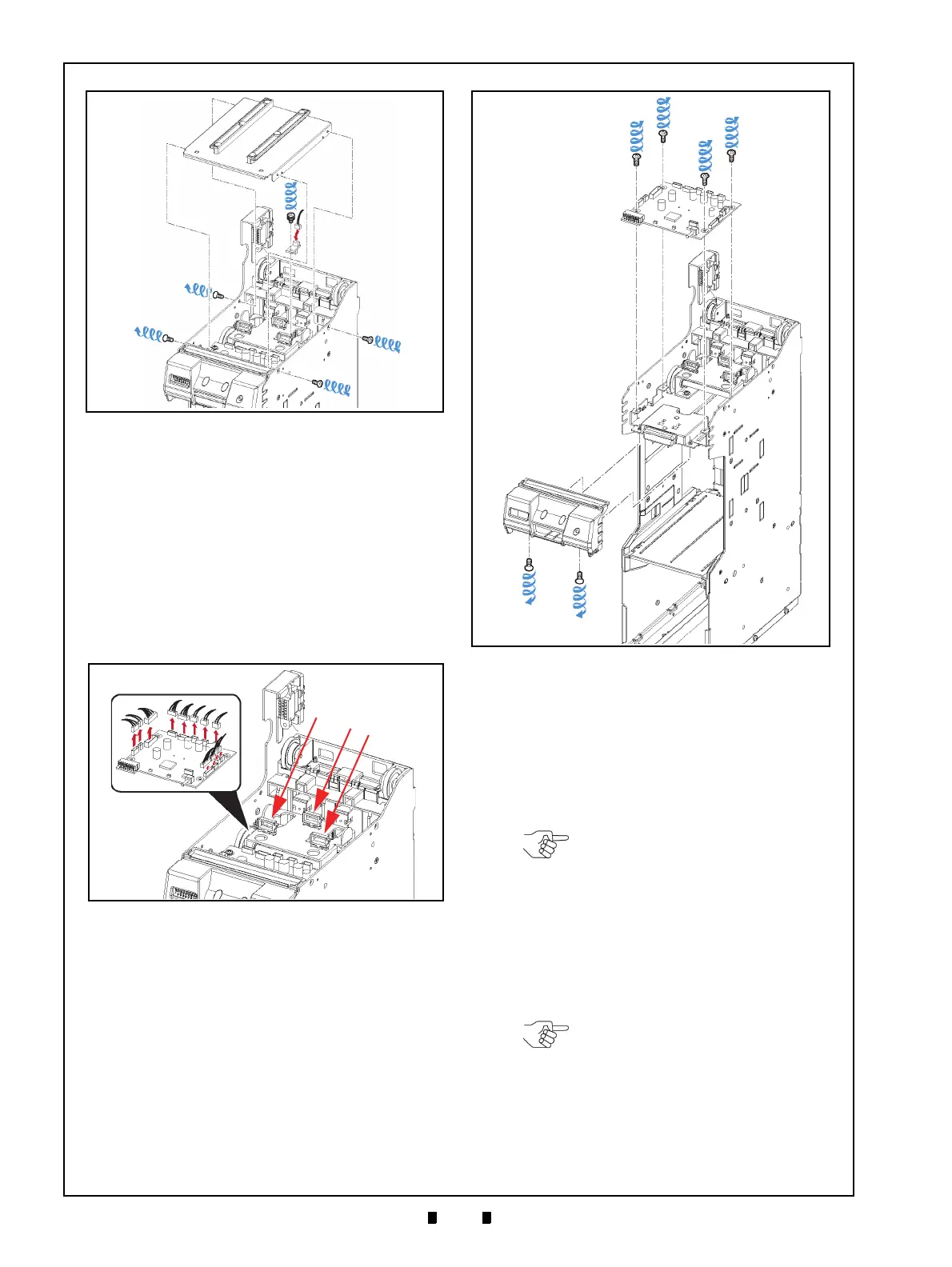
Recycler CPU Board
Assy Removal
To remove the Recycler CPU Circuit Board Assem-
bly, proceed as follows:
1. Unplug the twelve (12) Connectors (Figure 4-3 a)
from the Recycler CPU Circuit
Board Assembly
(Figure 4-3 b), and rem
ove the three (3) Har-
nesses from their three (3) related Retainer
Clam
ps (Figure 4-3 c
1
, c
2
& c
3
).
2. Remove the two (2) Mounting Screws (Figure 4-4
a
1
& a
2
) retaining the bottom of the RC Bezel
Assembly (Figure 4-4 b)
in place, and lift the RC
Bezel Assembly off of the Frame.
3. Remove the four (4) Mounting Screws (Figure 4-
4 c
1
to c
4
) retaining the Recycler CPU Circuit
Board Assembly in place (Figure 4-4 d) and
take
the Recycler CPU Circuit Bo
ard Assembly off of
the Frame.
Emission Side Double Note
Sensor Removal
To remove the Emission Side Double Note Sensor,
proceed as follows:
1. Remove the Frame Transport Guide (Figure 4-5
a) from the top
of the Frame.
2. Remove the Emission Side Double Note Sensor
(Figure 4-5 c) from
the Frame Transport Guide,
and unplug its single (1) Signal Connector (Fig-
ure 4-5 d).
Figure 4-2 Lifter Motor Encoder Circuit Board
Assembly Removal
Figure 4-2 Lifter Motor Encoder Circuit Board
Assembly Removal
Figure 4-3 Connector & Harness Removals
Figure 4-3 Connector & Harness Removals
Figure 4-4 Recycler CPU Circuit Board
Removal
Figure 4-4 Recycler CPU Circuit Board Removal
NOTE: When re-assembling the
Frame Transport Guide onto the
Frame, be sure to align the thick part
of the Frame Transport Guide to the
cut out area in the Frame (Figure 4-5
b).
NOTE: If the Sensor Assembly does
not remove easily, place the small
head of a Flat-blade Screwdriver
into the hole located on the back
side of the Frame Transport Guide,
and gently push the Sensor out of
the Frame (Figure 4-5 e).