P/N 960-000164R_Rev. 3 {EDP #213631} © 2018, JAPAN CASH MACHINE CO., LTD.
iPRO-RC™ Series
Banknote Recycler
Section 5
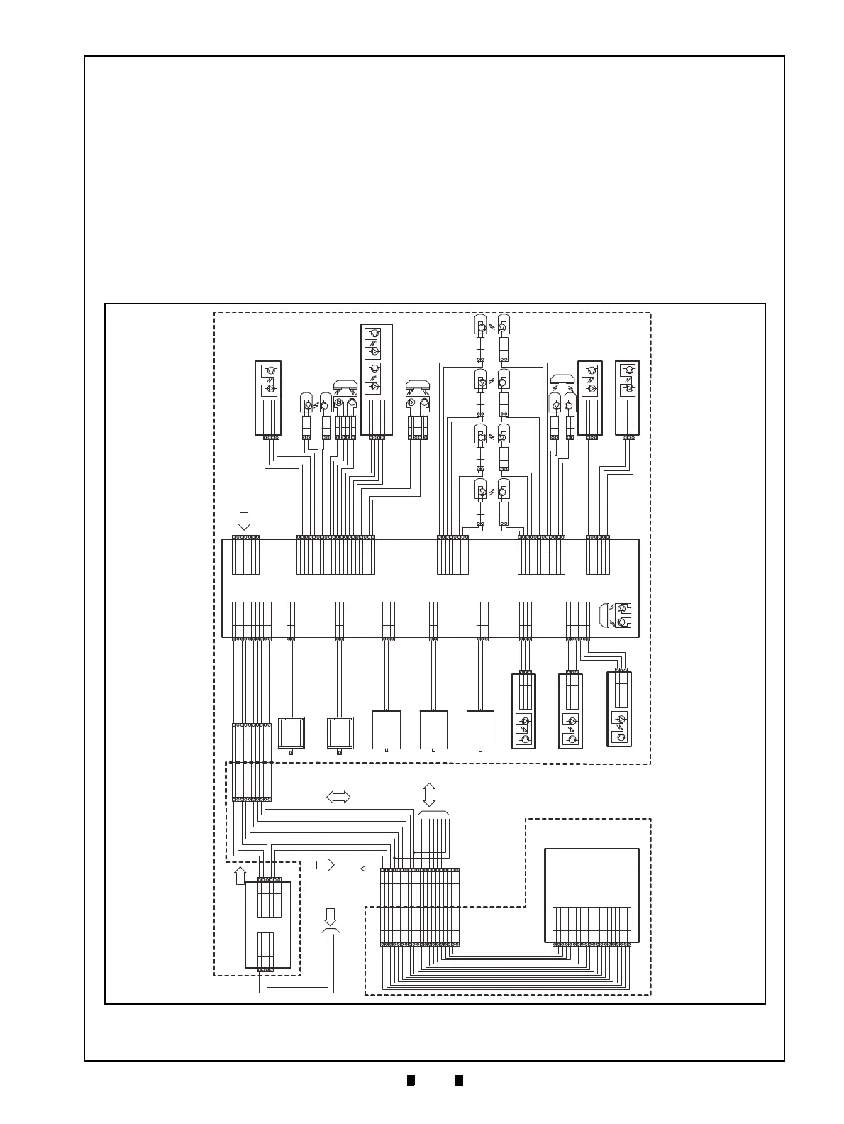
This section provides the iPRO-RC™ Series
Banknote Recycler (iPRO-100-SH2-RC; iPRO-
RC™) Unit wiring diagrams for the following
items:
• System Wiring Diagram
• Transport & Partial Frame Unit Wiring
Diagram 1
• Partial Frame Unit Wiring Diagram 2
Figure 5-1 iPRO-RC Entire System Wiring Dia-
gram (24V)
Entire System Wiring Diagram
CN1 CN2
13V Output
+24V
+24V
GND
GND
1
2
3
4
2B
3B
3A
1A
2A
1B
+13V
GND
13V I/F
+13V
GND
13V I/F
Power Source Circuit Board
Power Source
Harness
24V Input
13V
Output
Communication
Harness
Removable
Harness
5
2
1
3
15
11
17
20
13
4
6
7
14
16
18
19
8
9
10
12
13V
(I/F)
DCGND
13VDC (POWER)
M-RESET
I-TTL1
O-TTL1
I-TTL3
O-TTL4
SERIA L GND
SERIA L OU T
SERIAL IN
Opto GND
LED POWER
I-TTL2
O-TTL2
O-TTL3
USB Vbus
USB DM
USB DP
GND
(I/F)
13V (I/F)
DCGND
13VDC (POWER)
M-RESET
I-TTL1
O-TTL1
I-TTL3
O-TTL4
SERIA L GND
SERIA L OU T
SERIAL IN
Opto GND
LED POWER
I-TTL2
O-TTL2
O-TTL3
USB Vbus
USB DM
USB DP
GND
(I/F)
5
2
1
3
15
11
17
20
13
4
6
7
14
16
18
19
8
9
10
12
CN14
12
10
9
8
19
18
16
14
7
6
4
13
20
17
11
15
3
1
2
5
GND
(I/F)
USB DP
USB DM
USB Vbus
O-TTL3
O-TTL2
I-TTL2
LED POWER
Opto GND
SERIAL IN
SERIA L OU T
SERIA L GND
O-TTL4
I-TTL3
O-TTL1
I-TTL1
M-RESET
13VDC (POWER)
DCGND
13V
(I/F)
CPU Circuit Board
Serial
Communication
between
CPUs
Communicate
with
Gaming
Machine
1
2
3
4
5
6
7
8
9
10
1
2
3
4
5
6
7
8
9
10
+13V
GND
13V I/F
MRESET
TXD
RXD
RDY
MAIN RESE T
I/F GND
NC
+13V
GND
13V I/F
MRESET
TXD
RXD
RDY
MAIN RESE T
I/F GND
NC
Flapper Open/Close
Solenoid (Lower)
Flapper Open/Close
Solenoid (Upper)
Lifter Motor
Recycler Transport
Motor (Lower)
Recycler Transport
Motor (Lower) Harness
Recycler Transport
Motor (Upper) Harness
Recycler Transport
Motor (Upper)
Lifter Encoder
Harness
Centering Home Position
Sensor Circuit Board
(For Lifter Encoder)
Recycler Encoder
Circuit Board
(For Recycler Transport Motor Upper)
Recycler Encoder Circuit Board
(For Recycler Transport Motor Lower)
1
2
3
S16A
S16C
S16KE
1
2
3
S16A
S16C
S16KE
S5A
S5C
S5KE
1
2
3
CN1
CN1
CN1
CN4
CN6
1
2
3
4
5
61
2
3
4
5
6
S5A
S5C
S5KE
S6A
S6C
S6KE S7A
S7C
S7KE
S8A
S8C
S8KE
S16A
S16C
S16KE
1
2
3
7
8
5
6
3
4
1
2
9
10
11
12
S14C
S14E
S12A
S12K
S13C
S13E
S11A
S11K
S10A
S10K
S10C
S10E
UMOT+
UMOT-
NC
1
2
3
DMOT+
DMOT-
1
2
S11C
S11E
S13A
S13K
S12C
S12E
S14A
S14K
3
4
1
2
7
8
5
6
CN3
CN9
CN7
CN8
CN11
CN13
CN10
CN12
CN5
CN2CN1
LIFTMOT+
LIFTMOT-
NC
1
3
2
USND+
SUND-
1
2
USND+
SUND-
1
2
+13V
GND
13V I/F
MRSET
TXD
RXD
RDY
MAIN RESE T
I/F GND
NC
1
2
3
4
5
6
7
8
9
10
Vcc
GND
NMI
RES
P85
P86
P87
1
2
3
4
5
6
7
Vcc
S1A
S1C
S1KE
S2A
S2K
S2C
S2E
S3A
S3K
S3C
S3E
+5V
S9C
S17C
GND
S4A
S4K
S4C
S4E
1
2
3
4
5
6
7
8
9
10
11
12
13
14
15
16
17
18
19
20
Sensor Harness
Connected to Software Debug ICE
Vcc
S1A
S1C
S1KE
1
2
3
4
Transport Unit Encoder Circuit Board
CN1
S2A
S2K
1
2
S2C
S2E
1
2
S3A2
S3K
S3C
3
4
S3E1
Double Note
Detection Sensor LED
Double Note
Detection Sensor PT
Note Transaction
Detection Sensor 1
Box Detection Circuit Board
CN1
+5V
S9C
S17C
GND
1
2
3
4
S3A2
S3K
S3C
3
4
S3E1
Note Transaction
Detection Sensor 2
End Detection Sensor Harness
End Detection Lower
Sensor LED
Full Detection Lower
Sensor PT
End Detection Upper
Sensor LED
Full Detection Upper
Sensor PT
Full Detection Upper
Sensor LED
Full Detection Lower
Sensor LED
End Detection Upper
Sensor PT
End Detection Lower
Sensor PT
Lifter Home Position
Detection Sensor LED
Lifter Home Position
Detection Sensor PT
Full Detection
Sensor Harness
Flapper Open/Close
Detection Harness
Flapper Open/Close Detection
Circuit Board
(for Upper Flapper)
Flapper Open/Close Detection Circuit Board (for Lower Flapper)Recycler Circuit Board
Recycler Unit
Detection Sensor
Recycler Transport
Motor Encoder
Harness
S14A
S14K
1
2
S12A
S12K
1
2
S13A
S13K
1
2
S12C
S12E
2
1
S14C
S14E
2
1
S13C
S13E
2
1
S11C
S11E
2
1
S11A
S11K
1
2
S10A
S10K
1
2
S10C
S10E
2
1
S7A
S7C
S7KE
1
2
3
S8A
S8C
S8KE
1
2
3
CN1
CN1
Recycler Circuit Board
Power Source Harness
PT1 LED1
Figure 5-1 iPRO-RC Entire System Wiring Diagram (24V)