P/N 960-000164R_Rev. 3 {EDP #213631} © 2018, JAPAN CASH MACHINE CO., LTD.
Section 6 iPRO-RC™ Series Banknote Recycler Performance Tests
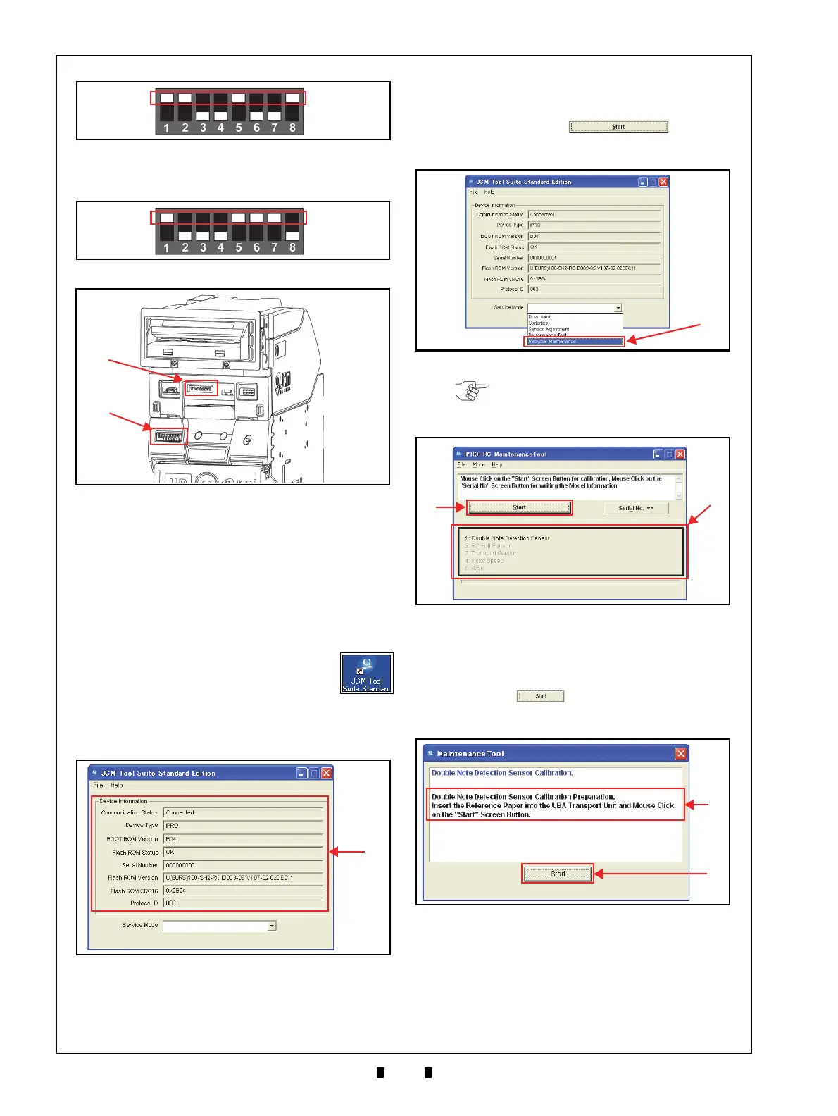
3. Set iPRO-RC™ 8-Position DIP Switches #1, #5,
#6 & #7 to ON (Figure 6-25 & Figure 6-26 b).
4. Turn the iPRO-RC™ Power Supply
ON. The two
(2) LEDs on the iPRO™ Transport Unit will light
a steady Green and Red Color, and the two (2)
LEDs on the iPRO-RC™ Unit will light a steady
Green Color.
5. Turn the iPRO™ Transport Unit’s 8-Position DIP
S
witch #8 to
OFF.
6. Connect the PC and the iPR
O-RC™ Unit together
using the recommended USB Cable.
7. Double-Click on the “
JCM Tool Suite
Standard Edition” Short-cut Icon on the
PC Desktop.
8. Launch the “
JCM Tool Suite Standard
Edition
” Application and the Model information
will begin appearing in the Device Information
Text Fields (Figure 6-27 a).
9. Click on the Service Mode Pull-down Menu and
select the “
Recycler Maintenance” Function (Fig-
ure 6-28 a).
10. Upon selection the “
iPRO-RC Maintenance
Tool
” Screen shown in Figure 6-29 will launch
automatically.
11. Click on the “
Start” Screen
Button (Figure 6-29 a) t
o begin the Calibration
and Performance Testing Procedures.
12. Insert a piece of KS-087 Reference Paper into the
iPRO™
Transport Unit Insertion Slot when the
message provided in the lower Text Field area of
the Screen (Figure 6-30 a) appears;
then click on
the “
Start” Screen Button (Figure 6-30
b) t
o begin the Double Note Detection Sensor
Calibration Procedure.
13. Confirm that the Test’s progress appears on the
“
iPRO-RC Maintenance Tool” Screen by view-
ing the Figure 6-31 a Green Progress Bar
.
14. The KS-087 Reference Paper will be returned
aft
er the Double Note Detection Sensor Calib-
ration Procedure is complete.
Figure 6-24 iPRO Transport DIP Switch Set-
ting
Figure 6-24 iPRO Transport DIP Switch Setting
Figure 6-25 DIP Switch Setting
Figure 6-25 DIP Switch Setting
Figure 6-26 DIP Switch Location
Figure 6-26 DIP Switch Location
Figure 6-27 Model Information Screen
Figure 6-27 Model Information Screen
Figure 6-28 Model Information Screen
Figure 6-28 Model Information Screen
NOTE: The available Calibration and
Performance Test items will appear in the
Black rectangular space below the Start
Screen Button (Figure 6-29 b).
Figure 6-29 iPRO-RC Maintenance Tool
Screen 1
Figure 6-29 iPRO-RC Maintenance Tool Screen 1
Figure 6-30 iPRO-RC Maintenance Tool
Screen 2
Figure 6-30 iPRO-RC Maintenance Tool Screen 2